Dowel pin shear strength is a property of the complete joint, not a number that can be assigned from diameter alone. Before selecting a pin, identify the load path, number of shear planes, clearance, support, host material, edge distance and expected service cycle. A catalog value or simple area calculation is only a screening input until the assembly is validated.
The practical question is not “what load can this diameter take?” It is “which failure mode governs this joint, and what evidence is needed before the drawing is released?” That framing prevents a nominal pin size from being treated as a universal rating.
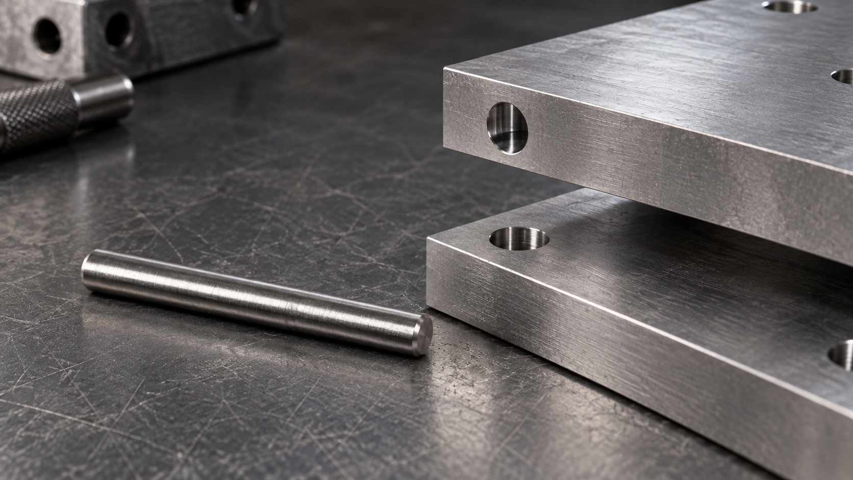
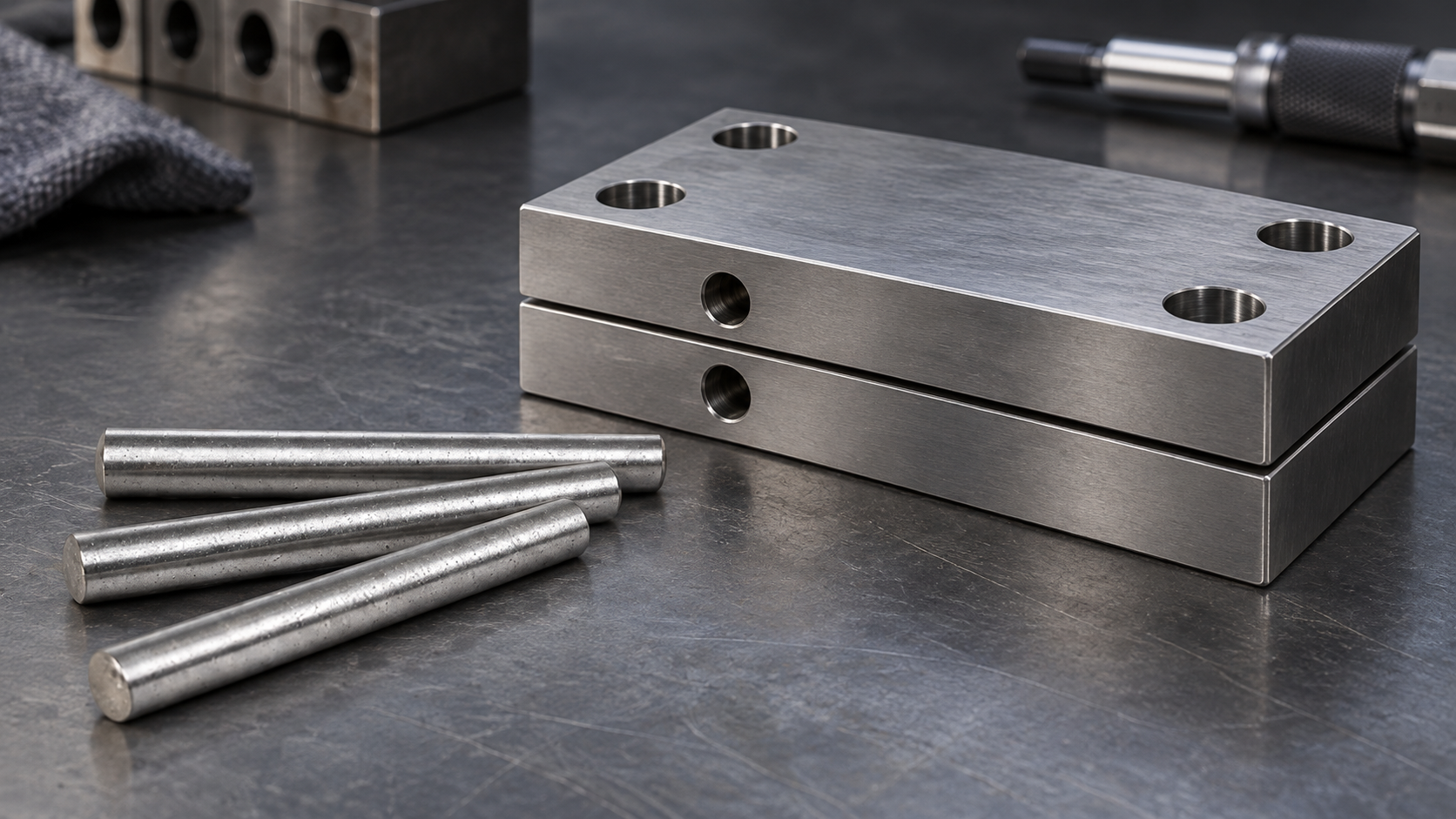
A pin in single shear has one principal shear plane. A pin in double shear has two load-transfer planes, but the surrounding plates, clearances and support thickness still control how the joint behaves. The pin may also experience bending when the supported sections are separated or when the load is offset.
| Factor | What to establish | Why it matters |
|---|---|---|
| Shear planes | Single, double or a more complex load path | Changes how load is transferred through the pin and supports. |
| Diameter and section | Actual pin geometry, not only nominal callout | Changes the available resisting section and local contact. |
| Clearance | Gap between pin and holes or between supported members | Can introduce impact, bending and uneven load sharing. |
| Host material | Strength, hardness, wall thickness and edge distance | The hole or surrounding material may fail before the pin. |
| Service loading | Static, shock, vibration, reversing or cyclic load | A static screen does not prove fatigue or dynamic performance. |
A simplified screening relation may begin with an applied shear load divided by the relevant shear area. That can help compare two candidate sizes, but it is not an allowable load calculation. The material strength, stress concentration, shear-plane count, bearing pressure and joint geometry still need approved values.
Do not insert a generic steel strength or safety factor into a production drawing. Different pin materials and conditions can have very different behavior, and the host assembly may govern first. The selected standard, material certificate, test data and design authority must define the release basis.
A larger diameter may reduce nominal stress, but it can also require a larger hole, reduce remaining wall, increase insertion force or change the assembly’s stiffness. The diameter should be selected with hole position, edge distance, support thickness and service access in the same review.
Separate the applied dowel pin load from the resistance used in the design check. The applied load may include direct shear, preload, impact or a reversing component. The dowel pin shear load is then shared through the actual contact surfaces, supports and shear planes. This is why a nominal static force cannot be transferred directly from one assembly to another.
When comparing dowel pin diameter options, record the unsupported length and the receiving-hole condition beside the nominal size. A larger dowel pin diameter can improve section capacity while reducing edge distance or increasing installation force. A smaller diameter may fit the envelope but leave the joint sensitive to bending, bearing or fretting. The selection is complete only when the pin, hole and host are reviewed as one joint.
For procurement, keep the design inputs with the part identity: material condition, standard or drawing revision, hole limits, supported length, loading direction and inspection evidence. A supplier can then review the same boundary conditions as the engineer. This is more reliable than asking for a “strong dowel pin” without the joint definition. It also gives the buyer a traceable basis for comparing quotations and approving substitutions.
Clearance between the pin and the receiving holes can delay contact and create a local impact when the parts move. A gap between supported members can also leave the pin spanning an unsupported distance. Under lateral load, that unsupported length can introduce bending before the intended shear planes carry the load.
Countersinks, chamfers, misaligned holes and soft host material can reduce the effective support area. These features are not automatically defects; they simply need to be included in the joint model. A drawing that controls only the pin diameter but ignores the holes cannot establish a reliable shear condition.
For repeated or reversing loads, consider wear, fretting, looseness and fatigue. A single successful static assembly trial is not evidence of long-term performance. Use production-intent parts and loading when testing is required.
Solid pins are often considered when the design needs a rigid locating element or increased resistance to bending and shear, but the selected material and condition remain application-specific. The pin can be strong enough while the host hole yields, enlarges or cracks. Review both sides of the interface.
TG Eugene’s site-listed cylindrical locating-pin family can be used as a sourcing route for a drawing review, but no product shear rating is established by the site facts used for this article. Confirm the exact standard, material condition, fit and inspection data before assigning a load to a specific part.
Use the dowel pin sizes and fits guide for dimensional inputs. A site-listed cylindrical locating pin should not be treated as a rated shear component without a released specification.
Not automatically. Diameter changes the pin section, but hole support, edge distance, clearance, host material, bending and the load path may govern first.
No. Diameter can support a screening comparison, but a release calculation needs the selected material data, shear-plane condition, host geometry, loading and validation basis.
Usually not. Manufacturer guides commonly state test conditions and limitations. Treat the value as bounded reference data unless the actual assembly and loading are covered by the approved design evidence.