A roll pin hole size chart should be read as a fit document, not as a single drill-number lookup. Match the pin family and nominal size first, then check the chart’s receiving-hole condition, unit system, edge preparation and inspection notes before machining the bore.
The free pin, the finished hole and the installed joint are different conditions. Confusing them can produce a hole that accepts the pin but does not provide the intended retention, or a hole that damages the pin during insertion.
| Step | Confirm | Do not assume |
|---|---|---|
| 1. Pin family | Slotted spring pin, standard and size | Every “roll pin” shares one chart |
| 2. Nominal size | Named diameter and unit system | Loose outside measurement is the hole size |
| 3. Hole column | Drill target, finished bore or fit range | A chart number applies without its notes |
| 4. Receiving material | Part material, thickness and bore condition | Steel, aluminum and worn holes behave identically |
| 5. Edge and inspection | Deburr/chamfer direction and final seating check | Release of the tool proves correct installation |
Slotted spring pins are designed to compress as they enter a receiving bore. That means the chart may show a nominal pin diameter and a separate recommended hole range. Use both fields as defined by the same source. Do not copy the pin’s free measurement into a drill program unless the selected standard or drawing explicitly requires it.
For metric work, keep the metric row and unit notation visible in the drawing or RFQ. If an inch chart is being used for comparison, record that it is a reference only and confirm the converted requirement before production.
Choose the machining operation from the approved hole requirement and the receiving material. A drilled hole may need a controlled finishing step when the drawing calls for a more consistent bore. A reamer is not a license to enlarge a hole beyond the approved range; it is a tool used within a defined process. That is why a press fit hole must be specified with its standard, material and inspection condition.
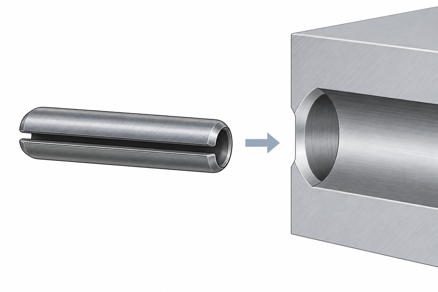
Before insertion, remove burrs and check the entry edge. A damaged or sharp edge can scrape the pin, obstruct insertion or create misleading resistance. The required chamfer or deburr method belongs to the drawing and process instruction, not to a generic chart summary.
Also check the joint after machining. A hole can meet a nominal chart row and still fail the assembly if the two parts are not aligned, the wall is too thin, or the pin is asked to correct a joint gap. Record those conditions with the hole requirement so the supplier and assembly team review the same problem.
“Metric roll pin” describes a unit system, not a complete purchase specification. Record the standard or part family, nominal size, length, material, finish and revision. ISO 8752 and DIN 1481 may appear in related spring-pin discussions, but the applicable source must be confirmed for the part being ordered.
TG Eugene’s ISO 8752 slotted spring pin page is a product-family route. For chart interpretation, use the site’s roll pin size and hole-fit guide; a controlled chart or drawing remains the final numeric source.
Match the pin family and nominal size to the approved chart or standard, then read the recommended-hole condition together with its units and notes. Confirm the receiving material, joint and inspection requirement before machining.
The unit system and size designation change, but the verification discipline does not. Keep the metric row, standard, revision and hole condition together; do not substitute a rounded value from an unrelated inch chart.