A dowel pin puller is selected from the pin’s access and engagement conditions, not from force alone. Through-hole pins may be driven from the back. Blind-hole pins need a designed extraction path, a suitable gripping tool, or a pull-out feature that accepts a screw or puller.
Start by identifying whether the pin is exposed, flush, damaged, or fully contained. Then check the pin diameter, available reach, surrounding clearance, host material and whether the assembly must be preserved. For a blind hole dowel pin, decide the engagement and reaction path before choosing the tool. Do not improvise a high-force removal method on a load-bearing or precision-located joint.
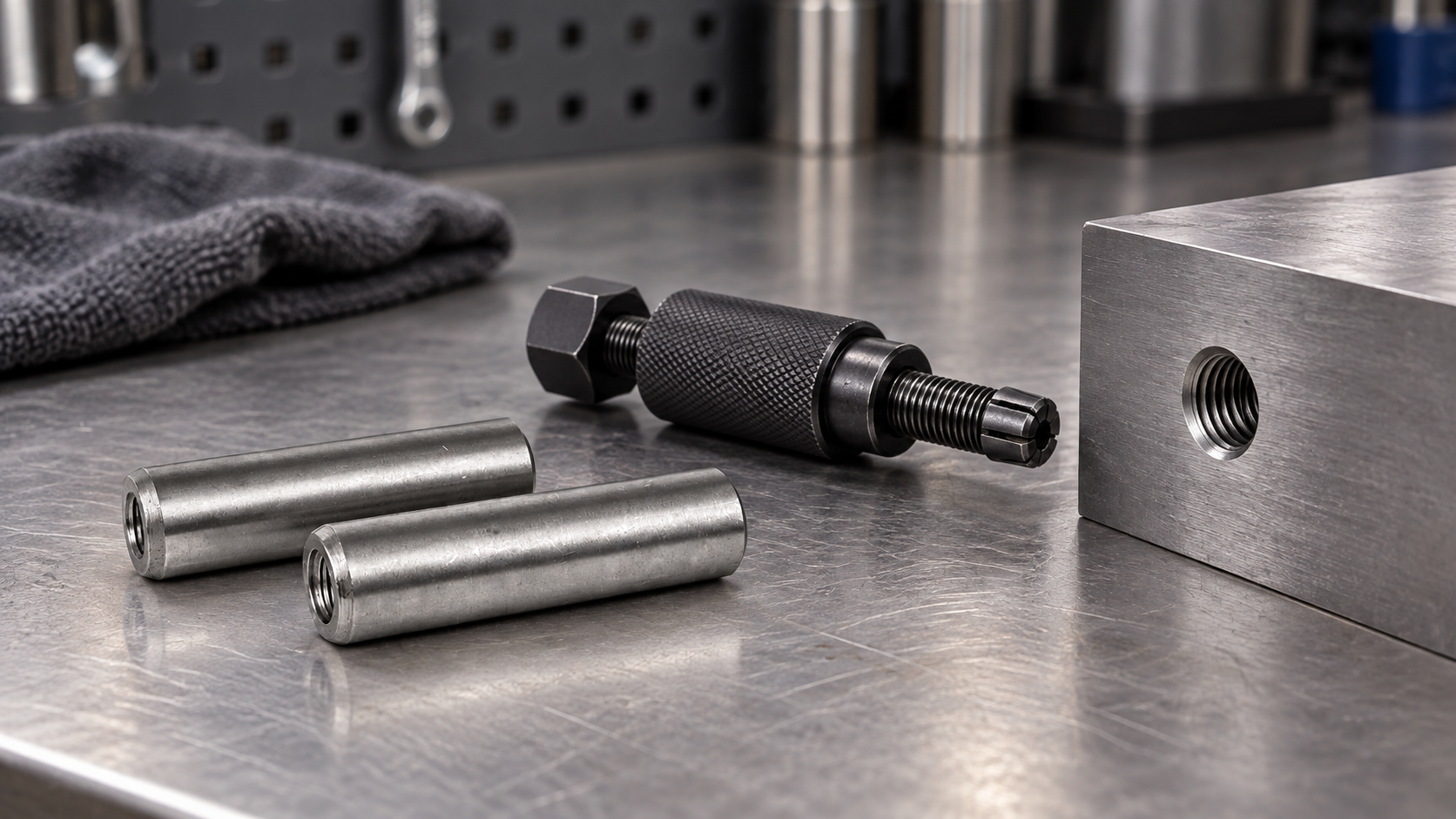
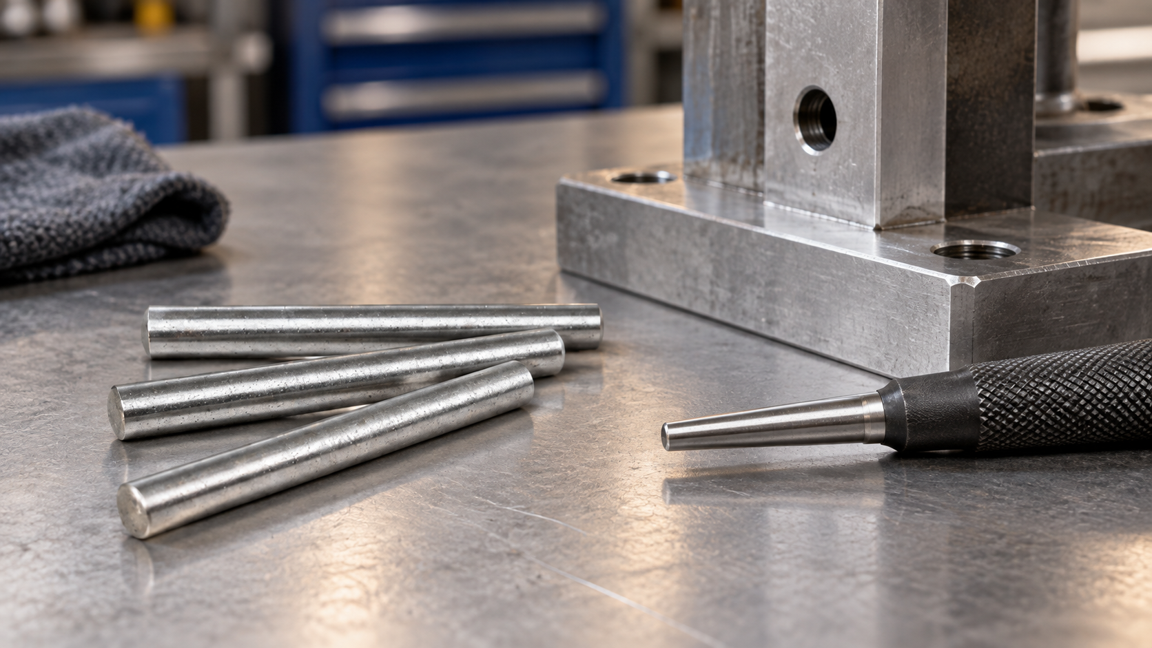
A puller transfers an axial extraction force to the pin through a controlled contact point. Common arrangements use a gripping collet, a threaded connection, a bridge and forcing screw, or a slide hammer. The exact capacity, reach and diameter range belong to the selected tool and must not be generalized from one product manual.
The first decision is whether the pin can be gripped without damaging the hole. A tool that clamps the exposed end may suit a protruding pin. A collet or internally threaded connection may be needed when the pin is flush or located in a blind hole. If there is no safe engagement surface, the correct answer may be a design change rather than a stronger puller.
| Condition | Possible route | Primary check |
|---|---|---|
| Through hole with rear access | Support the assembly and drive or press the pin out from the back | Support, alignment, punch diameter and risk to the exit edge |
| Exposed cylindrical end | Use a matched clamp, collet or puller attachment | Grip length, surface condition, reach and surrounding clearance |
| Flush pin in a blind hole | Use a designed threaded pull-out feature or a tool made for the exact access | Engagement depth, thread compatibility and hole protection |
| Damaged or seized pin | Stop for engineering review before drilling, heating or applying impact | Host material, load path, contamination and replacement plan |
A dowel pin removal tool is not automatically appropriate for every solid pin. The tool must engage the pin without transferring avoidable bending or side load into the housing. A puller selected by nominal diameter alone may have the wrong reach, collet range or access angle.
Compare the following inputs before ordering a dowel pin puller set:
Manufacturer instructions are the controlling document for a specific tool. For example, a commercial puller may state its own gripping range or slide-hammer arrangement. Those values should be treated as product-specific and should not be copied into a general specification.
A blind hole has no rear opening through which a punch can pass. If a pin must be removed during maintenance, the drawing should provide an internal thread, pull-out end, exposed shoulder or another planned access feature. A standard smooth pin placed in a blind hole can become a service problem even when the initial installation is successful.
Threaded pull-out dowels are one design route. An internally tapped end gives a screw, stud or puller a defined attachment point. It does not remove the need to check thread engagement, wall thickness, installation depth and the force path. If the hole is already blind and the pin has no pull feature, stop before creating a new thread without checking the remaining wall and alignment.
For a new design, compare the service cost of a pull-out pin with the cost of a separate tool, access hole, removable cover or sacrificial pin. The best choice depends on service frequency and the value of the surrounding assembly.
Do not use heat, drilling, welding or uncontrolled impact as a generic next step. These methods can change the host material, damage a precision hole or create debris. Record the failure mode and review the drawing if the pin is not removable with the intended process.
Removal is only half of the job. Before ordering a replacement, verify the original pin’s diameter, length, end form, material condition, surface finish and applicable standard. Inspect the hole for scoring, bell mouth, deformation and contamination. If the fit has changed, a replacement pin with the same nominal dimensions may not restore the original function.
For a threaded or serviceable design, include the removal feature in the drawing and RFQ. TG Eugene’s existing threaded dowel-pin guide covers the design-side trade-off. The site-listed cylindrical locating pin is a product identity route only; confirm the required material and standard for the actual replacement.
It depends on the available engagement and the surrounding assembly. A puller with a matched collet or a threaded pull-out feature may work, but no tool can be selected safely from the phrase “blind hole” alone.
Do not assume that more impact is safe. Check support, alignment, host material and tool instructions first. If the force path or assembly risk is unknown, stop for an engineering review.
If future removal is required, an internal thread or another defined pull feature can make the service path explicit. It must still meet the part’s wall, fit and load requirements.