A dowel pin press fit is a controlled relationship between the pin, receiving hole, host material and assembly method. It is not selected from the pin diameter alone. Before a drawing is released, define the fit intent, hole preparation, alignment, insertion method and inspection evidence for the actual joint.
The phrase dowel pin interference fit describes relative size and contact, but it does not supply a universal interference value. That value depends on the selected pin, host materials, section thickness, temperature, assembly force and service requirement.
The final dowel pin hole fit belongs in the controlled drawing with the pin, host material and inspection method identified together.
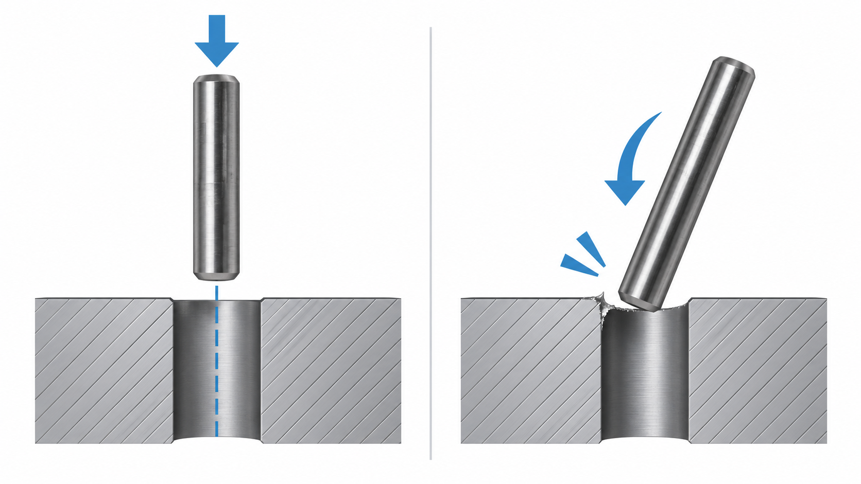
In a press fit, the pin is intentionally held by contact with the receiving hole rather than sliding freely during normal assembly. The fit can locate a component, resist movement or provide repeatable assembly positioning. The drawing must still state which component is the locating member and how the joint is serviced.
A press fit is different from a slip or clearance fit. It may require controlled insertion and may change the host material around the hole. If a joint needs frequent disassembly, a tight fit in every member may create an impractical service condition.
| Decision | Question to answer | Record in the drawing or work instruction |
|---|---|---|
| Locating function | Which member must return to position? | Locating member, datum scheme and assembly direction |
| Service function | Will the joint be removed or replaced? | Removal access and acceptable installation method |
| Hole process | How will the receiving hole be produced? | Process, inspection point and revision-controlled limits |
| Material pair | How will the pin and host respond? | Material condition, surface and compatibility requirements |
| Assembly | How will the pin enter without damage? | Alignment, support, tooling and stop condition |
Hole preparation is part of the fit. Confirm the tool path, hole position, roundness, cleanliness, edge condition and final inspection method. A reamed hole dowel pin application should not be specified only by naming the reamer; the actual hole requirement and measurement method still belong in the controlled drawing.
Remove burrs and contamination without changing the intended geometry. A chamfer can help guide entry, but it also changes the effective contact at the mouth of the hole. If the design depends on full support, keep the chamfer and edge break within the approved drawing limits.
Blind holes require additional attention to depth, trapped air, chips and the seating stop. Through holes require attention to the exit edge and support below the workpiece. Both cases need a defined way to reject a damaged or partially seated pin.
Before selecting a tight fit, decide how the assembly will be serviced. A locating pin may be installed once and retained for the life of the assembly, or it may need controlled removal during maintenance. The removal route affects access, end condition, hole damage risk and whether the pin should be treated as a replaceable item.
If the assembly is repeatedly opened, record the acceptable removal tool and the condition of the hole after removal. A process that works for a prototype may not be appropriate for production if it raises the surrounding material or changes the datum relationship. Include the service sequence in the drawing review rather than treating it as an operator preference.
The pin and host material should be considered together. A rigid pin can damage a softer host if the fit is too aggressive, while a weak or thin host can distort during insertion. Temperature can also change the relative dimensions of the two parts, especially where the assembly operates across a wide range.
Support the workpiece close to the hole and keep the insertion tool aligned with the pin axis. Do not use an impact method simply because the pin does not start. A pin that needs excessive force may indicate a wrong fit, damaged edge, misalignment or contamination.
Inspect the final position, seating, protrusion and nearby surface condition. Check that the mating components close as intended and that the pin has not raised material around the hole. If the joint requires repeatable location, measure the relevant datum relationship rather than only confirming that the pin is present.
Record the process condition that produced an accepted assembly. This can include the tool, support, sequence, inspection method and nonconformance response. The record is more useful than a general statement that the hole is “tight.”
Where the location is critical, verify the assembled datum relationship after both members are joined. Checking the pin alone can miss a shifted component, a raised edge or a hole that is nominally acceptable but out of position. The acceptance check should reflect the function the pin is meant to provide.
For first-article approval, record both the hole condition and the installation result. Note the drawing revision, pin lot, tooling, support arrangement and inspection method so the accepted assembly can be repeated. If the result changes between operators or workstations, treat that variation as a process issue rather than silently changing the fit. A short installation record also gives production and quality teams a common basis for deciding whether a damaged edge, incomplete seating or abnormal force requires containment.
TG Eugene’s DIN 1 cylindrical dowel pin page is a route to a product-family review. Confirm the exact drawing, material condition, fit, length and inspection requirements before ordering. The page does not establish a universal interference value for every assembly.
For a related hole-fit comparison, see the roll pin size and hole-fit guide. The product type and load path differ, so do not transfer a roll-pin recommendation directly to a solid locating pin. For an incomplete drawing, use the Service process to organize the missing inputs.
There is no single value for every assembly. The fit must be calculated and validated from the pin, hole, materials, section, temperature and installation method defined by the drawing.
No. Reaming is a production process, not a universal tolerance specification. Confirm the finished hole with the approved inspection method and the actual pin requirement.
Common causes include misalignment, burrs, contamination, an incorrect fit, insufficient support or a host material that cannot accept the selected relationship. Inspect the process before changing the pin blindly.