Laser engraving technology applications include part numbers, serial and batch identifiers, machine-readable traceability codes, equipment nameplates, control legends, tool identification and personalized graphics. Metals, plastics and organic materials need different laser/process combinations. The useful starting point is the application: what information must remain readable, on which material, and after which production or service conditions?
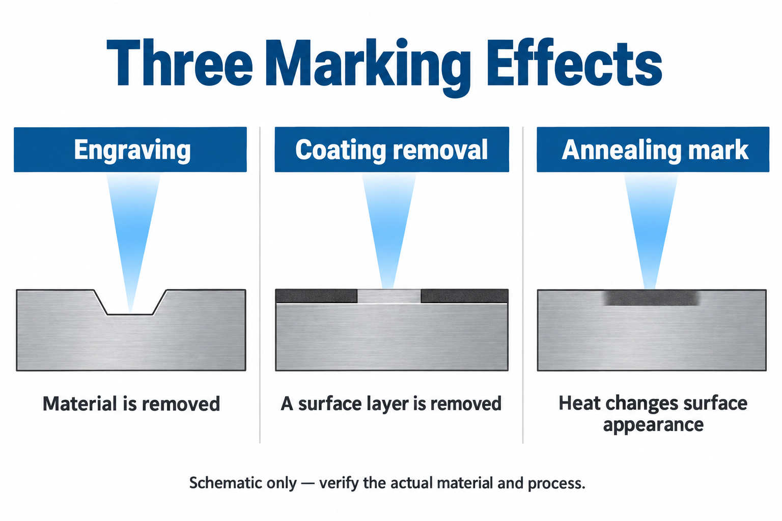
Begin with the required result: a recessed inscription, a contrasting mark in a coating, or a heat-induced color change. Those are different process effects. Matching the effect to the substrate and checking it after the relevant finishing steps is more useful than choosing a machine from a general list of laser types.
Engraving removes material. It produces a recess in the substrate. The question is whether that material removal is acceptable at the proposed location, not simply whether the inscription can be seen.
Coating removal targets a surface layer. A laser can expose a contrasting layer beneath a coating. The drawing and finish requirement should establish whether removing that layer is acceptable.
Annealing marking changes surface appearance through heat. It does not create an engraved recess by removing bulk material. It still requires process control: a smooth-looking mark should not be taken as proof that the original surface behavior remains unchanged.
| Application | What the mark must do | Material or process question | Useful acceptance check |
|---|---|---|---|
| Metal component identification | Keep a part or batch identifier readable | Is a recess allowed, or is another marking effect needed? | Read the mark on the finished part at its approved location |
| Coated plate or label | Create contrast for an identifier or legend | May the coating be removed in that area? | Check the intended contrast and finish condition |
| Plastic control or enclosure marking | Show symbols, labels or production information | Does the actual plastic and laser combination produce the required result? | Approve a sample made from the production material |
| Wood, acrylic or other graphic work | Produce a design, label or personalized surface | Which laser family and process suit that specific material? | Compare the real sample with the approved appearance |
The rows describe different jobs rather than interchangeable machine capabilities. A successful mark on one material does not establish the result on another material, coating or supplied condition.
Direct part marking can place identifiers on a metal component instead of a separate label. Define which identifier is needed: a part number distinguishes a component type, a serial number distinguishes one item, and a batch identifier links a production group. Choose a location that remains accessible for the intended reading task.
Data Matrix and other two-dimensional codes can carry an identifier for automated reading. The application includes both making the mark and linking its decoded content to the correct production record. Check the actual reader and part presentation; a visually neat code is not enough to prove that the intended system reads the right data.
Equipment plates and control surfaces need information that is clear to the operator. Contrast created by removing a coating can suit a plate or legend, while a different substrate may need another marking effect. Establish the exact text or symbols, their orientation and the approved finish rather than treating every nameplate as a deep-engraving job.
Identifiers on tools and production items help distinguish otherwise similar pieces. An illustrative fixture application might need its item code readable during setup without confusing it with a component serial number. Place the identifier where it supports that task, while checking whether engraving or thermal input is allowed on the selected surface.
Laser processes can mark selected plastics and create graphics on materials such as wood and acrylic. A plastic control part and a decorative wooden item have different priorities: one may need consistent symbol contrast, while the other needs an approved graphic appearance. Test the actual material and color; compatibility does not transfer automatically between plastics or laser families.
Fiber lasers are a common route for metal marking and engraving. CO2 systems are commonly used for materials such as wood and acrylic, while some coated-metal applications use a surface-layer process. The material, coating and intended effect determine which route deserves a trial.
The main advantages are non-contact marking, fine identification detail and compatibility with digitally controlled variable information on suitable materials. A serial-number application can change the marked data between items; a production workflow can link that data to its control system when the selected equipment and software support the interface.
These benefits serve different jobs. Fine detail helps fit readable information within an available marking area. Variable data helps distinguish individual items. Digital integration can reduce a separate manual data-entry step, but it also makes data mapping and sequence checks part of acceptance. Confirm those capabilities on the proposed system rather than assuming that every fiber laser provides the same workflow.
Non-contact describes how the beam acts on the part. It does not mean that fixturing is unnecessary or that material removal and heat have no consequences. Compare the finished mark, part location and production-data task together; a universal speed, depth or damage-free promise cannot replace that assessment.
A readable mark is only one part of an industrial component’s acceptance. For a thin strip, spring feature or working surface, establish whether material removal or local heating is allowed. Do not assume that a visually small mark is acceptable everywhere on the part.
Put the proposed location on the drawing and keep it clear of areas where the design does not permit a process change. Identify which dimensional, surface or functional checks are required after marking. The designer and processor should settle those checks on the actual material and supplied condition.
Intense heating during annealing marking on stainless steel can affect corrosion behavior. Verify the selected process and surface condition rather than treating a dark mark as proof of unchanged performance.
A serial number or code is useful only if the intended person or system can read it at the required point in the process. Define the content, location and reading method before approving the appearance.
For an illustrative setup, keep the part identifier, individual serial identifier and production-batch identifier as separate data fields. Approve a sample code, decode it with the intended reader, and compare the returned content with those fields. That checks both the physical mark and its meaning; it is not a report of an actual Eugene marking trial.
A camera or code reader may see a mark differently from the human eye. If machine reading is required, include it in sample acceptance rather than approving only a photograph of a high-contrast inscription.
For a component made from Eugene’s heat-treated spring steel strip, state the grade, supplied condition and surface requirement before a separate marking process is proposed. The material page is a starting point for that discussion, not a validated laser recipe.
Use the Eugene service process to send the material and component requirements together. Identify who is responsible for marking and which post-mark checks the order requires. This keeps the material supply decision connected to the finished-part requirement without assuming an unverified processing capability.
KEYENCE — laser applications and material/process families
Trotec — engraving, annealing and coating removal on metal
Trotec — annealing process and thermal-input considerations
Trotec — industrial identification, variable data and marking applications