Roll pin design starts with the joint and receiving hole, not the slot alone. Before a slotted spring pin is ordered, define the pin family, nominal diameter, length, hole condition, material, finish and inspection requirements. The slot helps the pin accommodate compression during insertion, but it does not replace a controlled fit review.
A useful design brief tells a supplier what is known, what is application-specific and what still needs confirmation. That distinction matters when “roll pin” is used as a workshop term for a spring pin, while the drawing must still identify the applicable standard and revision.
A slotted spring pin is a hollow cylindrical pin with a longitudinal opening. As the pin enters a receiving hole, the wall can compress around the slot and create a retained fit. The exact behavior depends on the pin family, nominal size, hole condition, material and joint geometry.
The slot is therefore one design feature, not a complete specification. A drawing that says only “roll pin” leaves open the diameter, length, standard, surface condition and acceptance method. It can also cause a buyer to copy a value from a chart that belongs to a different spring-pin family.
Describe what the pin is locating or retaining. Is it passing through aligned plates, entering a blind bore, or holding a component that sees vibration or repeated service? The answer determines which dimensions and inspection points deserve attention.
| Design input | Why it matters | What to record |
|---|---|---|
| Pin family and standard | Different families use different geometry and fit conventions | Standard, edition or drawing reference |
| Nominal diameter and length | Controls the basic envelope and engagement | Size, length and unit system |
| Receiving hole | Controls insertion and retained fit | Material, hole condition, through or blind bore |
| Joint and service condition | Changes access and inspection needs | Alignment, movement, vibration and replacement access |
| Material, finish and inspection | Sets purchasing and acceptance expectations | Material/finish requirement, quantity and inspection documents |
Do not select a hole by measuring only the loose pin. A spring pin chart normally distinguishes the nominal pin size from the recommended receiving-hole range. Read the column headings, units and fit notes together. If the hole is worn, burred, contaminated or already damaged, a nominal chart value may not describe the actual assembly condition.
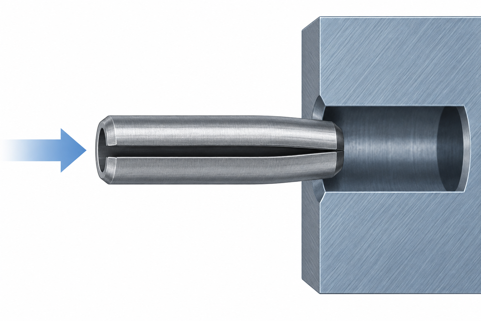
Record whether the hole is drilled, reamed or formed by an existing component. Note the entry edge and the available tool access. A clean lead-in can help the pin start without shaving material, but the required edge treatment must follow the drawing and application rather than a generic internet instruction.
A reviewable drawing or RFQ should make the following items easy to find:
When a customer has an existing part, include a drawing revision or a clear sample description. A supplier can then separate a standard ISO 8752 request from a drawing-based review instead of guessing which roll-pin family was intended.
Material and finish should be written as requirements, not inferred from a photograph. They can affect corrosion protection, handling, appearance and the way the part is accepted. If the application has a load or fatigue requirement, state the load case, cycle expectation and surrounding assembly conditions. Do not replace those inputs with a generic “heavy-duty” label or an unsupported load rating.
TG Eugene’s ISO 8752 slotted spring pin page is a product-family route. For related dimensions and receiving-hole context, see the roll pin size and hole-fit guide. Keep the terminology boundary separate from the design brief so the drawing stays focused on the selected part.
The slot allows a slotted spring pin to compress as it enters the receiving hole and recover against the bore. The resulting fit still depends on the selected pin, hole range, material and joint condition.
Identify the standard or revision, pin family, nominal diameter, length, units, receiving hole, material, finish, inspection requirements and quantity. Add the service or load conditions when they affect acceptance.