Threaded taper pins combine a locating taper with a threaded feature that can support service access. The first drawing question is not simply “what thread size?” It is whether the pin has an internal or external thread, which taper standard controls the body, and how the assembly will be installed and removed. Those functions must be specified separately.
An internally threaded taper pin has a threaded bore at one end. That bore can provide an engagement point for removal from a blind hole when the assembly and tool allow it. An externally threaded taper pin has a thread extending from the end and is specified for a different installation and retention arrangement. The names sound similar, but the drawing and service path are not the same.
| Drawing check | Internal-thread taper pin | External-thread taper pin |
|---|---|---|
| Thread position | Inside one end of the pin | Projects from the pin end |
| Typical service question | Can a removal tool engage without damaging the hole or thread? | Does the projecting thread fit the mating component and nut/fixture? |
| Body decision | Taper, nominal size, end and internal thread | Taper, nominal size, end and external thread |
| Evidence needed | Product drawing and thread specification | Product drawing and matching external-thread standard |
The selected TG Eugene page identifies a DIN 7979C internal-thread taper pin made from 40Cr, unhardened and ground. That gives the buyer a concrete internal-thread product path. It does not establish a universal thread dimension, pull-out force, removal torque or equivalence with every DIN taper-pin standard.
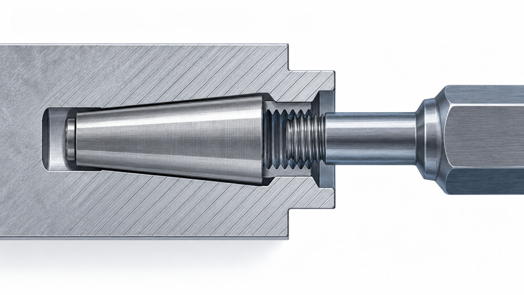
Start with the taper-pin standard and nominal size. Then identify the thread position and the exact internal or external thread specification. Add material and treatment only when the project has approved them. A callout that says only “threaded taper pin” leaves the supplier to guess a feature that changes installation and removal.
DIN 258 is a useful contrast because the current DIN Media record describes unhardened taper pins with metric thread ends and constant taper lengths. That is an external-thread reference. Do not transfer it to the DIN 7979C internal-thread route without a formal drawing or equivalence decision.
Check the receiving hole before driving the pin. Confirm that the taper, hole preparation, entry condition and engagement length match the approved drawing. Protect the internal thread during installation: the driving method must contact the intended pin end and must not damage the service feature that will be needed later.
Use the correct installation direction and a controlled tool. A taper pin should seat through its designed taper engagement, not through uncontrolled impact until the visible end happens to look flush. If the assembly uses a blind hole, record how the pin will be inspected and removed before production release.
The internal thread can give a removal tool a defined engagement point, but it does not make every stuck pin easy to extract. For taper pin removal, clear debris, confirm the thread is undamaged and choose a tool that fits the approved thread. Apply force along the pin axis where the assembly permits it. Avoid using the internal thread as a reason to exceed the host material’s safe load.
If the pin has seized, identify why before increasing force. Possible causes include burrs, corrosion, excessive interference, misalignment or damage from installation. The remedy may require a service procedure or a replacement decision rather than a larger tool. Record the condition so the drawing or process can be corrected.
For an internally threaded product route, review the TG Eugene DIN 7979C internal-thread taper pin page. For the broader distinction between taper and locating-pin standards, the site’s dowel pin standards guide provides the next reading path.
On an internally threaded taper pin, it can provide a controlled engagement point for removal from a blind hole when the thread, tool and assembly loads are compatible. It does not replace the taper fit or define a universal extraction force.