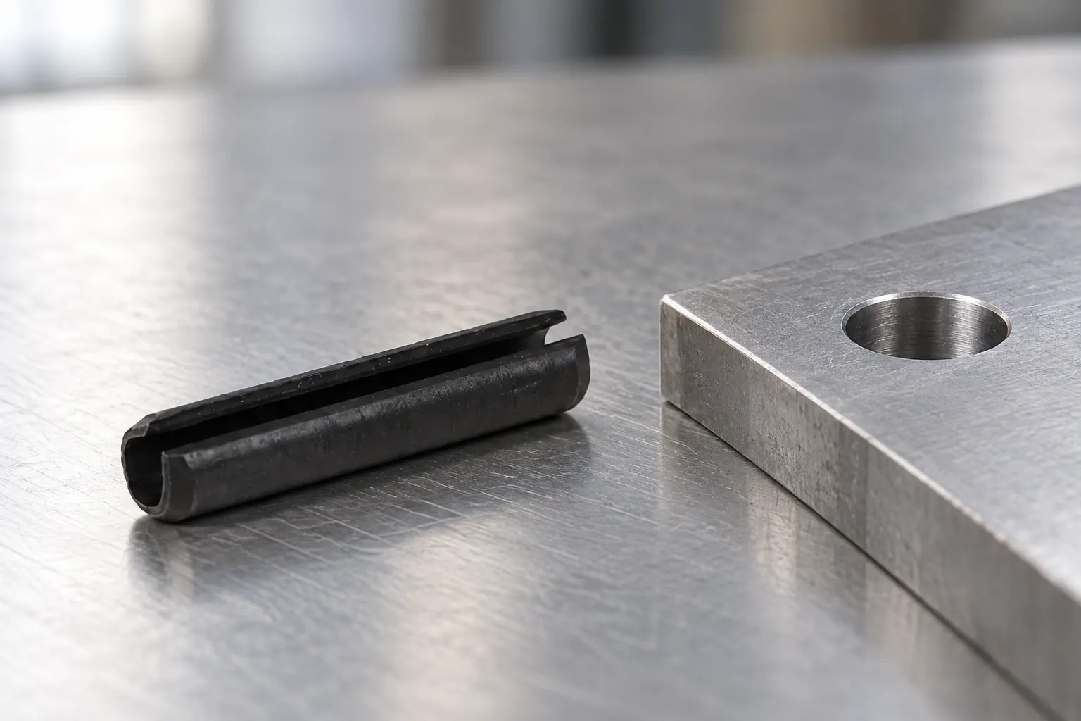
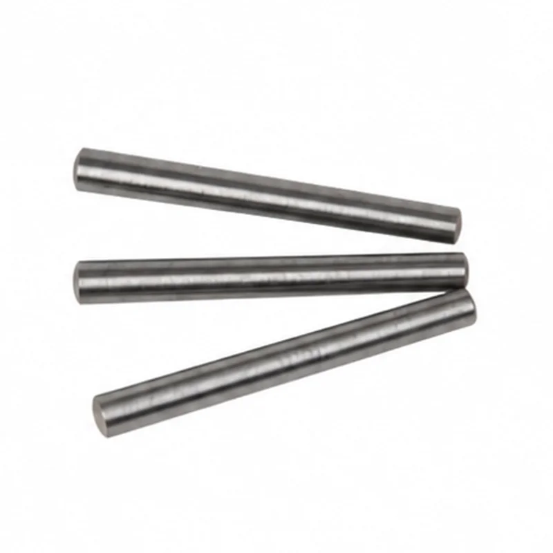
A dowel pin standard identifies the pin family, but the number alone does not complete a drawing or purchase order. Buyers still need to confirm the pin geometry, extraction feature, material condition, diameter and length, mating fit, and exact standard edition and revision.
That order matters. A parallel pin and a taper pin can have similar catalog descriptions while requiring different holes and assembly methods. Legacy DIN numbers also appear beside newer ISO references, so procurement teams should verify the official standard title before comparing dimensions.
The table below maps four common legacy DIN designations to their official pin families and successor references. Treat each successor as a route for further verification, not as proof that every dimension, end form, or designation stayed unchanged.
| Legacy designation | Official pin family | Successor family to check | First drawing question |
|---|---|---|---|
| DIN 1 | Taper pin | DIN EN 22339 / ISO 2339 | Does the joint require a taper rather than a constant diameter? |
| DIN 7 | Parallel pin | DIN EN ISO 2338 / ISO 2338 | Which pin tolerance and mating-hole fit are specified? |
| DIN 7978 | Taper pin with internal thread | DIN EN 28736 / ISO 8736 | Is the internal thread required for extraction from the large end? |
| DIN 7979 | Parallel pin with internal thread | ISO 8733 or ISO 8735 | Is the required material condition unhardened or hardened? |
This crosswalk prevents a common specification error: selecting a standard by a familiar number before confirming the physical form. It also keeps a withdrawn DIN designation from being treated as a complete modern callout.
A successor record identifies the modern family to investigate, but it does not prove that every length convention, end form, tolerance, or designation remained identical. A request written as “DIN 1 dowel pin” should therefore be checked against the official taper-pin title before anyone substitutes a current ISO reference.
When an existing drawing moves to a newer standard, record the old designation, proposed replacement, reviewed differences, and approval date in the revision history. Ask the supplier to acknowledge the exact edition quoted. This creates a traceable engineering change instead of an informal purchasing substitution.
A parallel pin keeps a constant nominal diameter along its working length. The designer controls the relationship between the pin tolerance and the mating-hole tolerance to obtain the required assembly behavior. The standard family, pin tolerance, and hole requirement therefore belong on the same controlled drawing.
A taper pin changes diameter along its length. Its seating behavior depends on the matching tapered hole and insertion direction. Replacing “taper pin” with “dowel pin” in an RFQ removes a critical geometry decision, even if the nominal size appears familiar.
Start with the assembly drawing. Identify whether the pin locates two parts, retains a component, acts as a pivot, or must be removed during service. That function does not select the standard by itself, but it tells the engineer which geometry and fit need to be controlled.
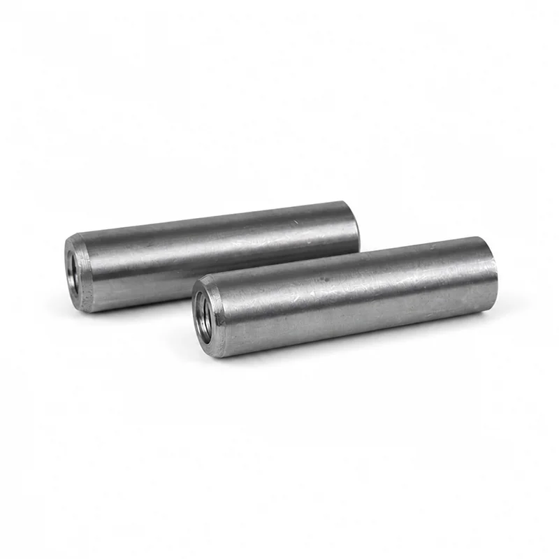
An internal thread provides an extraction feature. It does not convert a taper pin into a parallel pin, and it does not define the base material or hardness condition. This is why the DIN 7978 dowel pin and DIN 7979 dowel pin designations must be read with their official family titles.
For a blind installation, the drawing should identify where the thread is located and how it will be accessed. The purchasing specification should also separate the extraction thread from the locating diameter. They perform different jobs and require separate inspection.
Three decisions often get compressed into one catalog phrase. Keep them separate.
For example, ISO 8734 covers hardened parallel dowel pins. For parallel pins with an internal thread, ISO 8733 and ISO 8735 separate families by material and hardness condition. These ISO dowel pin standards still require the buyer to select the applicable product family and edition. Avoid shortening the requirement to “metric dowel pin” or “threaded dowel pin,” because those descriptions leave key inspection criteria unresolved.
The mating hole also needs its own controlled requirement. Do not assume that a pin standard automatically supplies the correct clearance, transition, or interference relationship for every assembly. The designer should select that relationship from the application requirement and record it on the part drawing.
Write the exact standard and edition. Record the full DIN, EN, or ISO designation rather than a family nickname. If an old drawing uses a withdrawn DIN number, note the intended successor family and confirm any differences before releasing the order.
Name the physical geometry. State parallel or taper. For an internally threaded product, also identify the thread location. This short description gives engineering and purchasing teams a direct check against the standard title.
Specify diameter and length using the governing convention. Do not transfer a length definition from one family or edition into another. End forms, chamfers, radii, and measurement points should match the selected document and drawing.
Control material and condition. State the approved material grade or material family and whether the pin must be hardened or unhardened. Add surface treatment only when it belongs to the approved product specification.
Define the pin tolerance and mating-hole requirement. The drawing should show which component retains the pin, which component must assemble over it, and whether service removal is expected. This prevents a supplier from guessing the intended fit from the standard number.
State inspection and document needs. Identify the dimensions or features that require inspection and list any material or process records required with the shipment. Keep these requirements proportional to the application; do not add certificates that the project does not use.
These six fields form a useful bid-comparison check. Two supplier quotations are not technically equivalent when they use different pin families, material conditions, tolerance classes, or standard editions, even if both quote the same nominal diameter and length.
The best specification is complete enough to prevent substitution, but narrow enough to leave the supplier a clear manufacturing route. Lock the interfaces that affect assembly: geometry, locating diameter, mating fit, extraction feature, material condition, end form, and inspection requirement. Avoid adding unsupported performance language or a copied dimension table.
After the drawing is controlled, buyers can review the TG Eugene product range and compare available locating-pin families against the approved requirement. Submit the drawing with the RFQ so the standard designation and visible product form can be checked together.