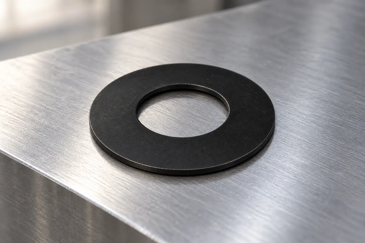
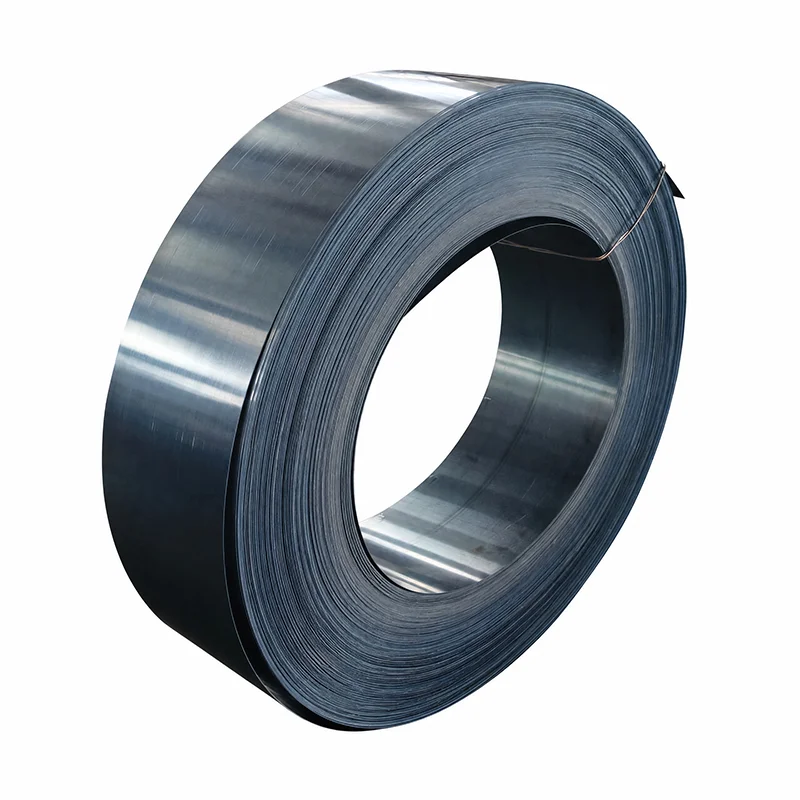
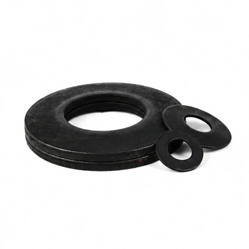
What is a Belleville washer? A Belleville washer is a conical disc spring that produces axial spring force as it deflects toward a flatter shape. Engineers use it when an assembly needs substantial force within a short axial space, controlled preload, or compensation for limited movement.
It may look like a dished washer, but it should be selected as a spring. The required load and deflection point, dimensions, material, support surfaces, travel limit, temperature, and service cycle all influence the choice.
A Belleville washer begins with a conical height. Axial compression reduces that height and creates spring force. Evaluate the required force at a defined deflection with verified data for the exact disc geometry and material.
The working point therefore matters more than a simple statement such as “heavy duty.” Define the force needed at the installed deflection and the permitted movement around that point. Evaluate that point with the manufacturer’s verified curve or calculation method for the exact disc.
Support conditions affect the result. The contact faces, guide, bolt, shaft, housing, and retained component must keep the disc aligned and provide suitable bearing surfaces. Rough, tilted, undersized, or flexible supports can change contact and load distribution.
| Part | Primary form | Typical design role | Selection focus |
|---|---|---|---|
| Belleville washer | Conical disc | Axial spring force in compact space | Load-deflection point, travel, support, and life |
| Flat washer | Flat ring | Load distribution or surface protection | Bearing area, thickness, material, and fastener system |
| Wave washer | Waved ring | Spring take-up at generally lighter loads and longer travel | Available space, force, deflection, and alignment |
| Coil spring | Helical wire | Spring force over a generally longer axial travel | Envelope, spring rate, guidance, buckling, and end support |
These roles can overlap, but the parts are not automatic substitutes. A flat washer is not a controlled spring. A wave washer and a Belleville washer can offer different force and travel behavior in the same envelope. A coil spring commonly needs more axial space and guidance for its travel, while a Belleville disc can provide substantial axial force within a short installed height. Compare the required force at defined travel, available diameter and height, guidance, support faces, and cycle requirement before changing the spring family.
For a deeper comparison, use the dedicated disc spring washer versus wave washer guide.
State the minimum and maximum force the assembly needs at defined positions. Separate installation preload from operating loads. If the force changes during service, show the full required range rather than one nominal value.
Define the installed height, available movement, and maximum permitted compression. Avoid planning routine operation at an uncontrolled flat condition. The selected product data should identify an approved working region and any travel limits.
Record outside diameter, inside diameter, free height, installed height, guide clearance, and adjacent component geometry. The disc needs room to deflect without rubbing, cocking, or trapping its edge.
Identify whether the disc is guided on an inside diameter, outside diameter, bolt, shaft, sleeve, or housing. Specify suitable contact faces. Check that the supporting parts can carry the concentrated load without unacceptable indentation or distortion.
Temperature, corrosion, lubrication, contamination, and relaxation requirements influence material and finish. A coating or alternate alloy should be supported by verified data for the intended environment and deflection range.
State whether the disc is loaded once, adjusted occasionally, or cycled repeatedly. Include expected force tolerance, dimensional variation, set, and inspection needs. Dynamic service requires a fatigue review of the actual stress range.
A single disc provides one load-deflection characteristic. Stacking discs changes the available force and travel. Discs placed in the same direction act in parallel and can increase force. Discs arranged in alternating directions act in series and can increase deflection. Mixed arrangements can combine both effects.
That principle is useful, but stack design needs more than counting discs. Friction between contact surfaces, guidance, alignment, tolerances, lubrication, and unequal load sharing can change actual behavior. Use verified stack data or calculation methods for the selected parts.
Stack design should remain a separate engineering task. Keep this definition page focused on deciding whether a disc-spring study is appropriate.
These examples identify questions, not universal product approvals. The assembly owner should validate the exact disc, supports, travel, and environment.
Begin verification with the released part identity and the dimensions controlled by the governing drawing or standard. Then verify spring force at the stated deflection using the applicable standard or the exact manufacturer’s approved method. A force result without its corresponding height or travel does not establish the required working point.
For a stack, confirm orientation, count, guides, and contact faces against the approved assembly before interpreting the result. The verification plan should also address the service conditions that matter to the design, such as static preload, repeated cycling, temperature, corrosion, relaxation, or fatigue. Use the governing standard, drawing, and approved test method to set procedures and acceptance limits rather than applying a generic test sequence.
Consider an assembly that needs preload after installation and allows additional movement in service. The design input should state the installed height, required force at that height, extra travel, and acceptable force at the second position. It should also define the available inside and outside diameter, guide arrangement, support faces, environment, and expected cycles.
A supplier can use those inputs to identify a candidate disc and provide the applicable load-deflection data. Engineering then checks both working positions, available clearance, travel limit, and service conditions before approval. This handoff is more useful than requesting a “strong Belleville washer,” because it links the spring choice to observable assembly conditions without assuming that one catalog size suits every preload task.
Include these fields when requesting a Belleville washer:
DIN EN 16983 defines quality specifications and dimensions for disc springs in the DIN system. Confirm that the current edition and its scope match the project before using a catalog designation as the complete drawing requirement.
After engineering sets the load and envelope, compare the verified TG Eugene disc spring product route and the broader product catalog. Send the required load-deflection point and assembly drawing with the inquiry.