Snap ring sizes describe an assembly relationship, not one free-ring diameter. The correct ring must match the shaft or bore, the groove diameter and width, available clearance, load direction, and installation method. Measuring a loose ring is useful for identification, but it cannot replace the groove specification.
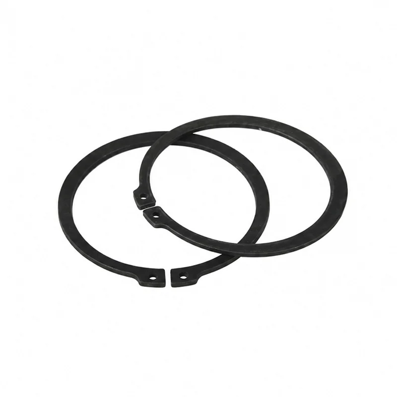
Start by deciding whether the ring is external or internal. An external ring installs in a groove on a shaft. An internal ring installs in a groove inside a housing or bore. The two families use different reference dimensions and cannot be exchanged because their free diameters look similar.
| Selection item | External snap ring | Internal snap ring |
|---|---|---|
| Installation location | Groove on a shaft | Groove inside a bore or housing |
| Primary nominal reference | Shaft size defined by the selected standard | Bore size defined by the selected standard |
| Groove controls | Groove diameter, width, corner condition, and shoulder geometry | Groove diameter, width, corner condition, and access inside the housing |
| Installation access | Tool expands the ring over the shaft | Tool contracts the ring into the bore |
| First verification | Confirm external-ring standard and shaft range | Confirm internal-ring standard and bore range |
For an unknown part, the ring’s lug orientation and installation location provide the first identification evidence. Record those observations before measuring. They narrow the search to the correct family, but they do not approve a replacement. Approval begins only after the shaft or bore, groove, standard, and service conditions are verified.
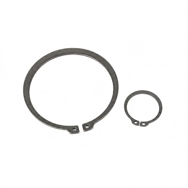
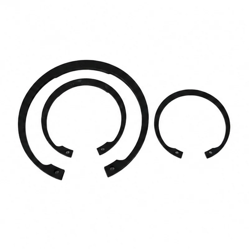
A loose ring changes shape during installation. An external ring expands; an internal ring contracts. Its free diameter therefore does not equal the nominal shaft or bore size. The exact relationship comes from the selected product standard and ring design.
Use free-ring measurements to narrow an unknown part, not to release a replacement. Record ring thickness, radial width, lug geometry, hole size, and free diameter. Then compare those observations with the correct external or internal family. Confirm the result against the machine drawing or a verified standard table.
Worn or distorted rings can mislead this process. A ring removed with excessive force may no longer return to its original free condition. If the part has been overloaded, corroded, ground, or permanently spread, do not use it as the only dimensional master.
Keep two columns in the replacement record: observed evidence and controlled requirement. The removed ring supplies observations. The unworn assembly, approved standard, and engineering decision supply the requirements. Never copy an observed value into a released drawing without completing that handoff.
This value identifies the assembly family. For an external ring, begin with the controlled shaft dimension. For an internal ring, begin with the controlled bore dimension. Do not swap these references when reading a supplier table.
Groove diameter controls how the installed ring sits radially. On a shaft, the groove diameter is smaller than the surrounding shaft surface. In a bore, it is larger than the surrounding bore. Inspect the correct feature and use the standard’s measurement convention.
Groove width must accommodate the ring thickness while controlling axial movement. Too little width can prevent seating. Too much width can increase movement and reduce the shoulder relationship needed by the design. Include coating and finishing effects when they change the finished groove.
Ring thickness and radial width affect strength, flexibility, and groove compatibility. Do not substitute a ring with the same outside appearance but a different cross-section. Verify the exact size row and tolerance set.
The retained component needs enough clearance from the groove shoulder and ring lugs. Groove corners, chamfers, housing steps, and adjacent radii can block full seating. The assembly drawing should show these interfaces instead of leaving them to inspection judgment.
In the identification column, record the loose ring’s free diameter, thickness, radial width, lug form, hole form, finish, and condition. In the approval column, record the nominal shaft or bore, groove dimensions and tolerances, selected standard row, ring material and finish, retained-part clearance, and service inputs. A candidate passes identification when its form and measurements are plausible. It passes approval only when every controlled interface is supported.
A larger ring is not automatically safe for a larger axial load. The ring, groove, shaft or housing material, edge distance, retained component, and loading mode act together. Repeated, shock, or reversing loads may need a different review from a steady axial load.
Use the ring manufacturer’s or governing standard’s verified capacity method for the exact configuration. Compare ring capacity with groove capacity and the strength of the surrounding component. Apply the design factors and test requirements approved for the application.
Environmental conditions also matter. Corrosion can reduce ring section and prevent clean seating. Temperature can affect materials and coatings. Contamination can hide a partial seat. Add these conditions to the selection record when they affect service.
Record rotational speed when the ring operates on rotating equipment. RPM can change the loading and retention review, especially for an external ring on a shaft. Do not apply a generic speed limit. Verify the exact ring, groove, shaft material, assembly geometry, load, and operating speed with the governing method or manufacturer data.
Identify the installation. Confirm shaft or bore, ring type, removal direction, and tool access.
Measure the controlled base feature. Record the shaft or bore in an unworn area with suitable equipment.
Measure the groove. Check diameter, width, corner condition, depth relationship, burrs, and damage.
Inspect the removed ring. Record section dimensions and visible form, but treat free diameter as identification evidence only.
Confirm the standard and size row. Use the current approved document. Do not mix dimensions from different ring families.
Verify assembly behavior. Confirm full seating, retained-part clearance, and the acceptance checks required by the design.
If the original drawing is missing, mark the replacement decision as an engineering review. A catalog match based only on two measurements can overlook groove tolerances, material requirements, or load limits.
Choosing by free diameter. A loose ring is not in its installed condition, and a used ring may be distorted. Start from the controlled shaft or bore and the groove.
Mixing external and internal table columns. Similar labels can describe different reference features. Confirm the installation family before reading any dimension row.
Checking groove diameter but not width. The ring can appear seated while axial clearance, coating buildup, or a narrow groove prevents proper shoulder contact. Inspect both dimensions and the corner condition.
Ignoring the retained component. A correct ring and groove can still fail the assembly task if the retained part contacts the lugs, lacks shoulder area, or applies load outside the intended path.
Reusing a removed ring without approval. Installation and removal can permanently spread, contract, twist, or scratch the ring. Use the project reuse rule and inspect the part before considering reinstallation.
Copying a capacity value across materials. Ring and groove capacity depend on the specified materials and geometry. A value for one size, alloy, or housing condition does not approve another configuration.
A short design review can catch these errors before tooling or purchasing begins. Put the selected standard row, ring identity, groove dimensions, surrounding material, load case, and installation method in one approval record.
Attach the identification record to the engineering review. It should show which values came from the removed ring, which came from the assembly, and which remain unknown. Then release the approved requirement—not the measurements of the used sample—to purchasing.
This handoff makes the page different from a general snap-ring selection guide. Its purpose is to convert an unknown or legacy ring into traceable evidence, resolve the governing assembly data, and prevent a visually similar catalog part from becoming an uncontrolled replacement.
For terminology and family selection, review what a snap ring is. If the design uses a DIN 471 external ring, the DIN 471 dimensions and installation guide owns that detailed standard-specific task.
After the groove is defined, compare the verified DIN 471 external ring and DIN 472 internal ring routes. The full TG Eugene catalog can support family identification, while the approved assembly drawing controls final selection.