When deciding how to use a lock washer, identify its type, place it against the contact surfaces specified for that design, and tighten the joint to its approved assembly requirement. A split spring washer, a toothed washer and a wedge-locking pair do not use the same mechanism. Their installation arrangements are not interchangeable.
The washer normally belongs beneath the relevant nut or bolt head, but that does not establish the complete stack. Confirm whether the joint calls for direct contact, a plain washer, a matched pair or washers at both ends before assembling it.
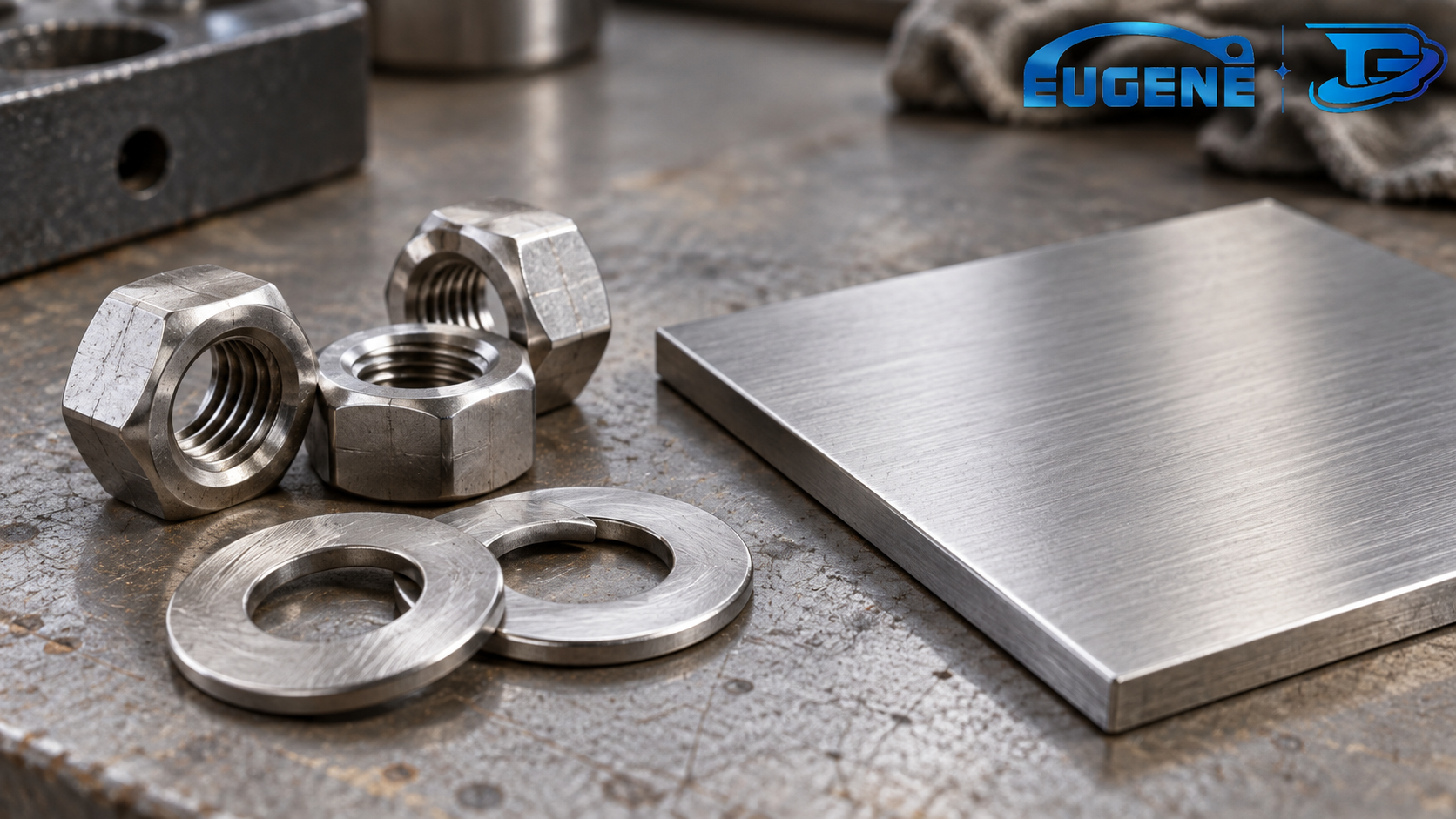
A split lock washer is a helical ring with offset ends. A toothed washer has edges intended to engage its contact faces. A wedge-locking system uses a specified pair of washers with a different internal interface. A smooth conical disc spring is another component again: its spring-load function does not automatically make it a locking device.
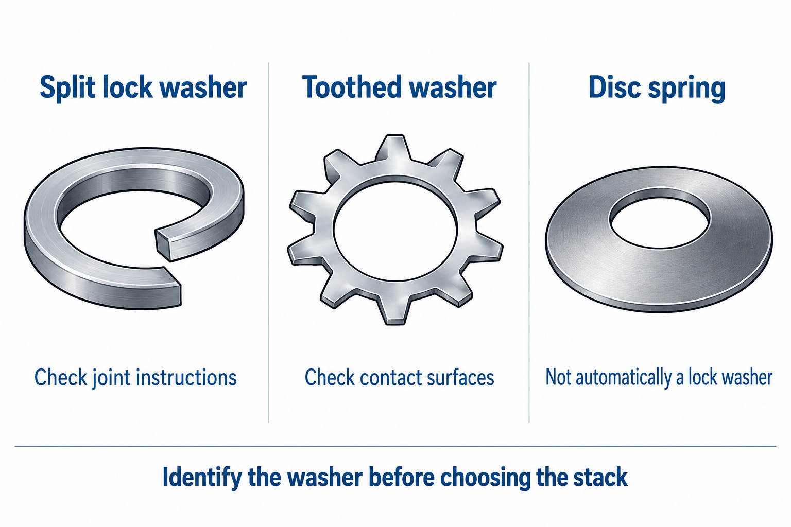
Use the part number and drawing to complete the identification. Appearance alone does not establish material, hardness, finish, compatibility or reuse permission. A loose washer from an unidentified box is not an adequate replacement instruction.
| Washer type | Placement decision | Limit to check |
|---|---|---|
| Helical split washer | Follow the specified position beneath the nut or head and the complete approved stack | Its presence does not establish dependable vibration locking |
| Toothed or serrated washer | Identify the faces the teeth must engage | An added loose plain washer can change those contacts; surface damage may matter |
| Wedge-locking pair | Keep the specified pair and manufacturer-defined interfaces together | Check the actual joint arrangement, including whether both ends require pairs |
| Smooth Belleville disc spring | Use the load-and-deflection arrangement specified by the design | Do not assume its spring force provides an anti-rotation qualification |
For a particular serrated safety-washer design, SCHNORR’s fitting guidance calls for direct contact between the washer, the nut or head, and the clamped component. It specifically excludes adding a plain washer or stacking those safety washers. That is a product-specific instruction, not a reason to remove a plain washer from an unrelated approved assembly.
Check the specified type, nominal size, material and finish against the parts supplied. Confirm that the washer fits the intended fastener and bearing area without substituting a different type simply because its center hole fits.
If the original instruction only says “lock washer,” resolve the missing type and arrangement before proceeding. That short description does not establish which locking mechanism the designer intended.
Compare the parts with the drawing or manufacturer’s installation guide. Identify the nut or head that bears on the washer, the underlying surface and every additional washer in the stack. Check for visible damage or missing components against the applicable inspection instruction.
Do not add a flat washer as an automatic improvement. It changes the interface beneath a locking element. Where the approved drawing specifies both a plain and a locking washer, retain that exact arrangement rather than borrowing instructions for a different washer system.
Follow the specified orientation and position. For Nord-Lock’s original wedge-locking system, the cams face each other within the pair and the outside serrations engage the mating faces. Its through-hole guide uses a pair under the bolt head and another under the nut. Do not transfer that two-pair arrangement to every washer sold under the general “lock washer” name.
Use the tightening method, tool and lubricant condition specified for the actual joint. There is no universal torque value for a washer type alone. Do not reduce the required tightening just to leave a visible gap in a split washer.
If the required torque or assembly condition is unknown, obtain the missing instruction. A visual impression that the washer looks compressed is not a substitute for the required tightening control.
Confirm that the correct components are present and seated in the specified arrangement. If a washer has been removed, use the manufacturer’s inspection and replacement criteria for that product. Do not apply a blanket “all lock washers can be reused” or “all must be discarded” rule.
The mechanism matters more than the name. NASA’s 1990 Fastener Design Manual explains that a typical helical spring washer acts as a spring during tightening, but ordinarily becomes flat at full tightening. Its discussion says that this washer no longer provides locking action in that state. That limitation concerns the typical helical design described; it is not a finding that every locking-washer system behaves identically.
The same manual distinguishes tooth washers, whose edges engage the opposing faces and can damage those surfaces. For a finished or coated component, that contact is part of the engineering decision, not an incidental cosmetic detail.
A wedge-locking pair uses another arrangement. Its internal cam interface and outer serrations must remain in the manufacturer-defined relationship. Removing one half or inserting another component into the pair changes the system being installed.
For a joint with a specified vibration-locking requirement, use an approved locking solution and its applicable evidence. The fact that an assembly contains a split washer does not demonstrate that requirement has been met.
A flat washer, locking element and disc spring answer different design questions. Do not build a stack by collecting one of each. Establish the intended bearing contact, locking function and spring-load requirement first, then use the approved combination.
A DIN 2093 Belleville disc spring is relevant when the design calls for an axial spring function. The DIN designation does not by itself establish a bolt-locking qualification. The separate Belleville spring washer selection guide addresses that load-and-selection task.
Suppose a maintenance note says only “replace nut and lock washer.” A useful clarification identifies the washer part number, the fastener size and finish, the required contact faces, the full stack, the tightening instruction and the replacement or reuse criterion.
That handoff resolves the questions an installer actually faces without inventing a torque value or changing the joint. If the supplied parts do not match the clarified instruction, resolve the discrepancy before assembly.