How to remove a dowel pin depends on access, pin geometry, hole condition and whether the pin can be pulled or driven. Start by identifying the joint rather than applying more force. A through-hole may allow a controlled drive from the opposite side; a blind hole may require a puller or a threaded extraction method. Stop if the bore, alignment surfaces or surrounding part begin to deform.
| Condition | Preferred first route | Main protection point | Stop condition |
|---|---|---|---|
| Accessible through-hole | Support the part and drive from the open side with a correctly sized drift | Keep the drift centered and protect the bore mouth | The pin mushrooms or the drift starts to mark the hole |
| Blind hole with exposed end | Use a controlled puller or approved threaded extraction method | Keep pull force aligned with the bore | The pin rotates without moving or the tool starts to tilt |
| Threaded dowel | Confirm the internal thread and use the matching extraction interface | Protect the thread from cross-loading | The thread strips or the pin is not the assumed size |
| Taper pin | Drive from the small end after confirming orientation | Support the surrounding boss or plate | The small end is inaccessible or the joint starts to spread |
Clean the area so the pin end, surrounding bore and any retaining feature are visible. Record which component is allowed to move and which surface must remain aligned. A locating pin is not automatically a spring pin, threaded pin or taper pin. Compare the exposed geometry with the drawing or maintenance record before choosing an extractor.
Measure only what helps identify the existing part. A caliper reading across a damaged end is not a reliable nominal diameter, and an exposed length does not prove the buried length. If the pin is part of a controlled assembly, photograph the joint and preserve the removed part for replacement review.
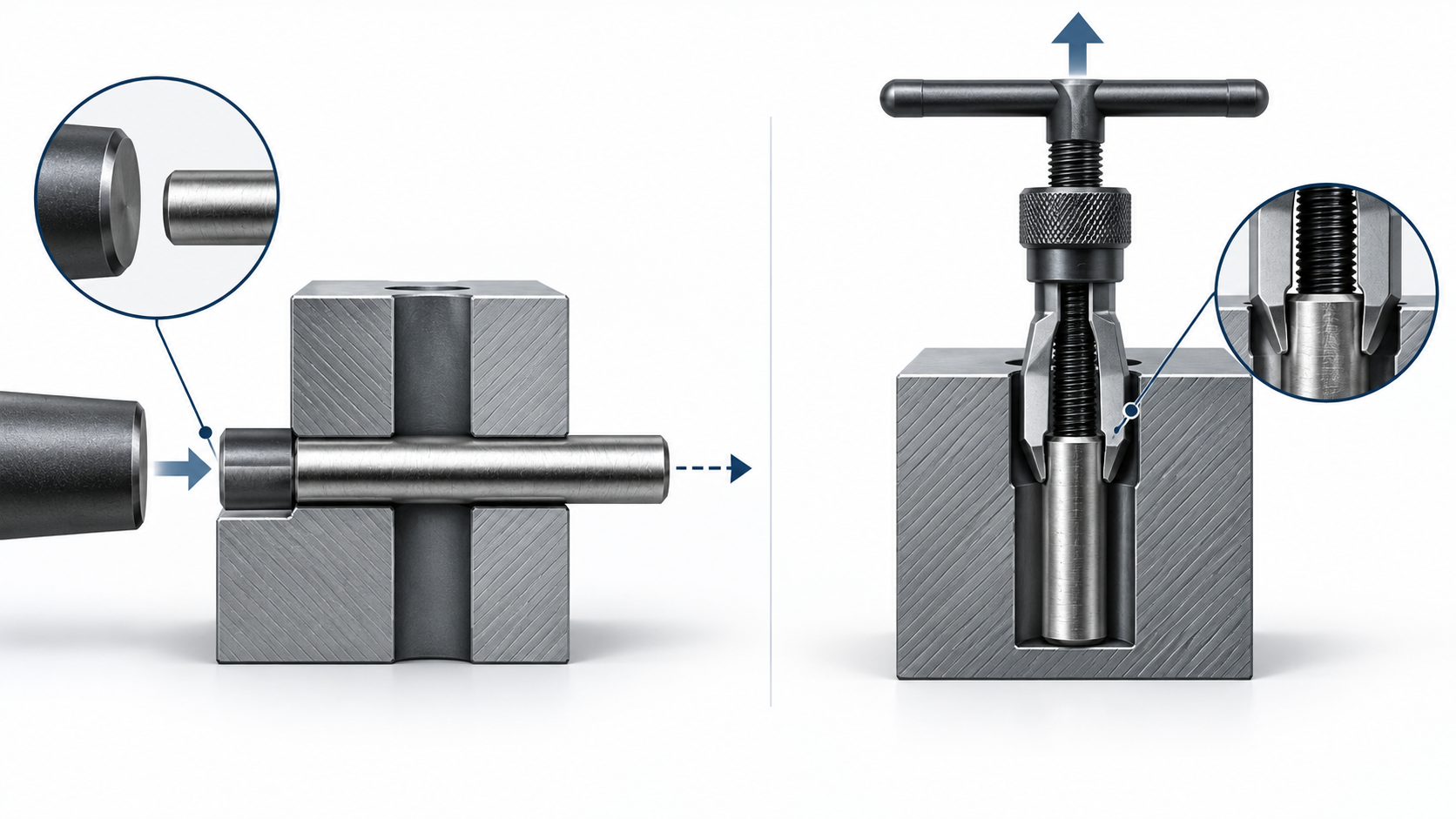
Support the component close to the hole so the driving load does not bend a thin plate. Select a drift that contacts the pin end without touching the bore wall. Keep the drift square to the hole and use short, controlled strikes or a press stroke. Recheck alignment after the first movement. The goal is to move the pin through the existing bore, not to enlarge the opening.
Do not use a loose punch that can slide across the pin end. Do not drive against a thin unsupported flange. If the pin end is peened, corroded or visibly smaller on one side, stop and decide whether the assembly needs a different extraction tool or a repair procedure.
A blind hole removes the easy driving path. If the pin has a suitable internal thread, use a puller or extraction screw that matches the thread and stays coaxial with the bore. If the pin is plain, a specialist extractor may be required, but the tool must be selected for the actual pin and hole condition. A generic screw forced into a plain pin can expand the pin, damage the bore or leave chips at the bottom.
Apply load gradually and watch the relationship between tool, pin and housing. A puller that tilts can turn a straight extraction into a side load. Protect the housing face with a bridge or washer only when the support surface can carry the reaction load. If the pin does not move, stop rather than increasing force without a new plan.
Threaded locating pins need an extraction interface that matches the thread. The DIN 7978 internally threaded locating-pin family shows why thread geometry is part of the product definition; it is not evidence that an unidentified pin has the same thread.
Taper pins should be driven in the correct direction. Confirm the large and small ends from the drawing or the exposed geometry, then support the surrounding material. A taper pin that has been forced from the large end may wedge harder and spread the hole. For a replacement, compare the taper form and the mating-hole condition rather than ordering by length alone.
After removal, clean chips and raised material from the bore mouth. Check for scoring, bell-mouthing, peening, corrosion and a visible change in alignment. Use the drawing’s inspection method where one exists. A pin that came out successfully can still have left a hole that no longer supports the original fit.
Record the original pin family, diameter designation, length, material or finish information, and whether the hole is through or blind. TG Eugene’s DIN 1 cylindrical locating-pin family, DIN 7 taper-pin family and threaded family provide separate routes; they should not be treated as interchangeable because the word “dowel” appears in a search.
If the hole or pin identity is uncertain, send the drawing, hole condition, access direction and removed-part photos for a drawing and fit review. A replacement decision needs more than an extractor size. It may require a controlled diameter, length, material, finish, hardness condition or standard edition.
Use the least damaging route that matches the access and pin type: a centered drift for an accessible through-hole, or a coaxial puller or approved threaded method for a blind hole. Support the work and stop when the tool begins to tilt or the bore starts to mark.
No. Extractors depend on pin geometry, exposed length, thread condition and bore access. A plain, threaded and taper pin may require different methods. Confirm the actual pin before selecting a tool.