A dowel pin with head adds a head, flange or shoulder that changes how the part seats and how it enters the assembly. That feature can provide a stop, a seating surface or a handling aid, but it also changes clearance and removal requirements. Specify the head geometry, locating diameter, hole, shoulder and assembly direction together.
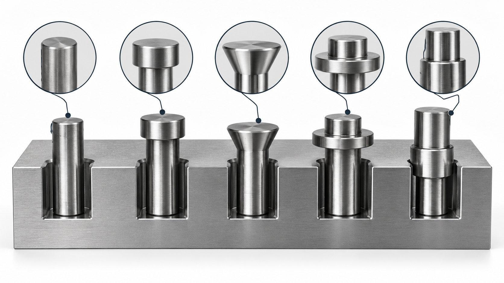
| Form | Possible function | Design question |
|---|---|---|
| Headed pin | Provides a positive stop or limits insertion depth | Can the head seat flat without interfering with the mating part? |
| Flat-head pin | Creates a low-profile stop or bearing face | Is the head diameter and thickness compatible with clearance? |
| Flanged pin | Adds a wider seating or locating surface | Does the flange change the load path or block access? |
| Shouldered pin | Separates a locating diameter from a larger stop diameter | Which diameter locates, and which surface controls seating? |
A straight locating pin relies on its cylindrical or tapered relationship with the holes and any defined seating depth. A headed form adds another controlled surface. That can make the assembly more repeatable, but it can also create a new interference if the mating part, washer, fastener or tool needs space around the head.
Do not route every headed-pin search to an engine repair part. The phrase “dowel pin with head” is broader than a cylinder-head replacement. This article addresses general geometry, fit and installation; engine-specific service requirements remain a separate application.
Start with the locating diameter and its hole relationship. Then define head diameter, head height, shoulder length, total length, chamfers and any relief. A drawing should show which surface stops the pin and which diameter provides location. If those roles are not clear, a supplier may quote a visually similar part with the wrong functional dimensions.
Consider the host material and insertion method. A headed pin pressed into a blind hole may bottom before the locating section is fully seated. A flange can mask a burr or prevent inspection. A shoulder may create a stress concentration or require a counterbore. These are design checks, not values that can be inferred from the keyword.
Review the stack-up with the head in its final seated position. Include the mating surface, washer or fastener clearance, tool approach and any thermal or service movement. A head that looks helpful in a standalone sketch can interfere once the surrounding assembly is shown.
Show the direction of insertion on the drawing. If the head is the installation stop, confirm that the tool can push on the correct surface without damaging the finish. If the pin must be removed later, include an extraction route, exposed feature or service-side access. A head can help removal in one assembly and block it in another.
For a taper form, the large and small ends still control the seating relationship. TG Eugene’s DIN 7 taper-pin family is a separate standard route from a headed straight pin. Do not add a head, shoulder or taper to a purchase request unless the drawing calls for it.
Material and finish affect fit, corrosion behavior and the condition of the seating surfaces. State whether the locating surface must remain ground, whether a coating is acceptable and which surfaces are inspection-critical. Do not assume that a head and a locating shaft share the same finish requirement without checking the design.
Inspect the features that control function: locating diameter, head or flange diameter, shoulder length, total length, surface condition and seating. For a controlled standard route, compare the drawing revision with the product record. TG Eugene’s DIN 1 cylindrical locating-pin page is a reference for a straight locating family, not a blanket certificate for every headed geometry.
When the head is fabricated or drawing-specific, ask the supplier to identify the inspection datum. The same nominal length can be measured from the head face, shoulder or end, and those choices are not interchangeable in a controlled stack-up.
Keep that datum consistent across quotation, first-article inspection and repeat orders. Otherwise a dimensional result may be correct from one reference surface and wrong for the assembly’s seating requirement.
Use the drawing review service when the head is non-catalog, the shoulder controls a stack-up, the hole is blind, or the assembly uses dissimilar materials. Include a section view and the insertion/removal direction. A complete drawing prevents the broad phrase “headed dowel pin” from becoming an incomplete quote.
No. A cylinder-head dowel is an application-specific part. A headed dowel pin is a broader geometry description. Confirm the engine, drawing, dimensions and service requirements before treating them as the same.
Not automatically. The head may stop or seat the pin, while the locating diameter controls alignment. The drawing must define the intended load path and contact surfaces.