Threaded dowel pins are used when a locating pin must do more than align two parts: the assembly also needs a defined service path. An internal thread can give a tool an engagement point for removal from a blind hole, but it does not replace the cylindrical fit, material, standard or hole-control requirements of the dowel pin.
A plain dowel pin may be easy to install but difficult to remove when there is no access to the opposite end. Internally threaded dowel pins change that service condition by allowing a compatible tool or puller to engage the pin from the accessible side. The benefit is practical only when the thread, tool, host material and direction of force are specified together.
| Selection question | What it controls | What not to assume |
|---|---|---|
| Is the hole blind? | Whether one-sided removal access is needed | A thread guarantees removal from a seized hole |
| What is the locating fit? | Alignment, insertion and retention in the host | The thread determines the cylindrical fit |
| What is the material state? | Wear, contact and service compatibility | A generic “hardened pin” description applies to every route |
| What does the drawing state? | Standard, size, thread and inspection | All DIN/ISO internal-thread pins are interchangeable |
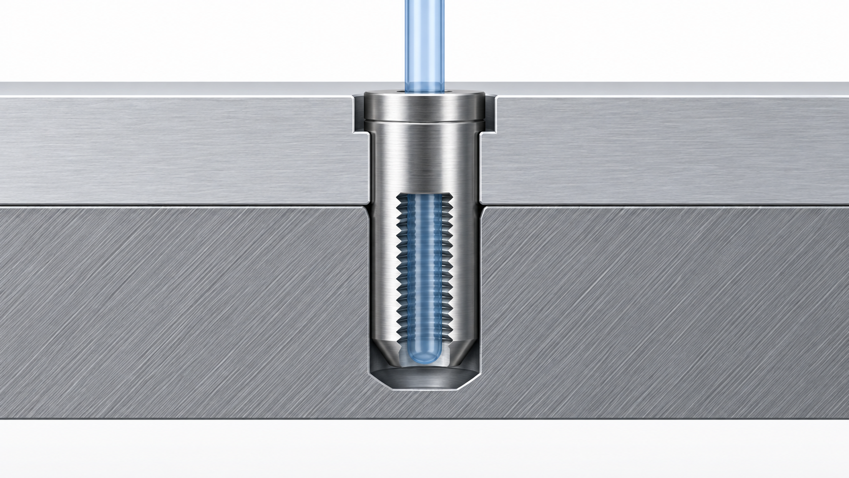
The internal thread is a service feature; the outside diameter and receiving hole still control location. Before selecting a threaded dowel pin, confirm the hole process, diameter tolerance, engagement length, mating materials, edge condition and whether the parts must be repeatedly separated.
Do not solve a loose fit by choosing a larger internal thread. The thread may make removal possible, but it does not correct a hole that is oversized, misaligned or damaged. If the assembly needs a specified locating fit, keep that requirement visible in the drawing and inspection plan.
The selected TG Eugene product route is a DIN 7978 internal-thread dowel pin described as 40Cr, bright and unhardened. That is the relevant first-party description for this article’s product pathway. ISO 8735 is a separate current standard record for parallel pins with internal thread in hardened steel or martensitic stainless steel. It should not be silently used to re-label the TG Eugene route.
For purchasing, write the actual standard and material condition required by the project. If the product is being used in a wear-sensitive or repeatedly serviced joint, request the drawing and certificate needed to verify the selected condition rather than relying on the phrase “threaded dowel pin.”
Prepare and inspect the receiving hole before installation. Keep the pin aligned with the hole, protect the internal thread from driving damage and use the approved installation method. The pin should seat through the intended cylindrical fit, not through uncontrolled force until the visible end happens to reach a preferred depth.
Record the installation direction and any tool access limit. If the pin is installed in a blind hole, the same access decision should appear in the service procedure. That avoids a common handoff failure: production can install the part, but maintenance cannot engage the feature later.
Use a compatible removal tool that fully engages the internal thread and applies force along the pin axis where the assembly allows it. Before increasing force, check for corrosion, burrs, misalignment, excessive interference or thread damage. A larger tool or sudden impact can damage the thread, host hole or surrounding component.
If the pin cannot be removed through the approved path, stop and record the failure condition. The next action may be a controlled service procedure, a drawing change or replacement of the assembly. The internal thread improves access; it is not a guarantee of successful extraction under every seized condition.
Review the TG Eugene DIN 7978 internal-thread dowel pin page when the specification matches that route. For the next sizing step, use the site’s dowel pin sizes and fits guide, then confirm the final callout against the approved drawing.
The internal thread can provide one-sided service access, especially when a dowel pin sits in a blind hole. It does not replace the outside-diameter fit or make all internally threaded pins equivalent.
Use a compatible tool that engages the internal thread and applies controlled axial force after checking for corrosion, burrs, misalignment and thread damage. The exact tool and allowable force depend on the approved drawing and assembly.