DIN 472 covers retaining rings installed in bore grooves, but the standard number alone does not define a release-ready order. A drawing or RFQ should also state the applicable edition, ring type and size, bore and groove geometry, material, hardness group, surface treatment and required inspection evidence. The current DIN Media record lists DIN 472:2026-05 and shows that it replaced the 2017-06 edition.
The detailed values in this guide are taken from the client-held DIN 472:2017-06 reference edition. They are useful for understanding the control logic, but they must be checked against the purchased current edition before contractual use. No current TG Eugene batch certificate was supplied, so the article separates standard-reference values from supplier and lot evidence.
A DIN 472 ring is an internal retaining ring. Installation pliers contract it so it can enter a bore, after which the ring expands into an internal groove. Once seated, it forms a removable shoulder that limits axial movement of a bearing, sleeve or another retained component.
DIN 471 is the complementary shaft-ring route: an external ring is expanded over a shaft and released into an outside groove. The two families are not interchangeable. Their free geometry, installation direction, groove location and contact with the retained part differ. A drawing should use internal or bore terminology consistently so that the product, groove and inspection plan all point to the same configuration.
The assembly designer still owns the bore and groove tolerances, wall thickness, edge distance, retained-part corner, axial load, rotation, temperature, environment and service access. The ring and groove each have a load limit; the lower one controls the joint. A nominal ring size therefore cannot replace an assembly calculation or a review of the housing material.
The DIN 472:2017-06 reference edition specifies C67S or C75S spring steel under DIN EN 10132-4. That statement describes the reference edition; it does not prove the material of a particular production lot. A DIN 472 retaining ring order should identify the permitted circlip material. Where traceability matters, define the required inspection certificate, heat or batch identification and document linkage in the purchase order.
The same reference edition separates hardness by bore-diameter group. It does not assign one HRC value to every DIN 472 ring:
| Bore diameter group, d1 | Vickers hardness | Rockwell hardness | Use boundary |
|---|---|---|---|
| d1 ≤ 48 mm | 470–580 HV | 47–54 HRC | DIN 472:2017-06 reference edition |
| 48 mm < d1 ≤ 200 mm | 435–530 HV | 44–51 HRC | DIN 472:2017-06 reference edition |
| 200 mm < d1 ≤ 300 mm | 390–470 HV | 40–47 HRC | DIN 472:2017-06 reference edition |
The report should identify the correct size group, test method and scale. ISO 6507-1:2023 is the current Vickers-method record, while ISO 6508-1:2023 covers Rockwell testing. In the 2017-06 product reference, Vickers is decisive if the result is disputed. Keep that rule linked to the edition rather than treating it as a general statement about every specification.
Spring steel hardness must also be read with function. A compliant reading does not by itself demonstrate correct set, flatness, crack resistance or grip. Heat treatment can produce the target hardness yet leave a formed spring part with distortion or brittleness. A sound release package combines material identity, heat-treatment result, dimensions and functional inspection.
The DIN 472:2017-06 reference edition lists a phosphate-coated-and-oiled route under DIN EN ISO 9717 and a blackened-and-oiled route under DIN 50938. A purchase description should use a controlled finish designation. Terms such as “black finish” are too broad to define process, coating thickness, oil condition, appearance or corrosion-test expectation.
For the phosphate-and-oil route, the reference edition lists no corrosion after eight hours of neutral salt spray. That is an edition-specific laboratory acceptance condition. It does not mean eight hours predicts storage or service life. ISO 9227 defines salt-spray methods, but actual corrosion depends on environment, packaging, condensation, chemicals, abrasion, maintenance and the assembled geometry.
Other coatings may be possible, but their thickness can change the finished ring thickness and seating in the groove. Buildup on the ring faces or near the lug area can affect assembly. The drawing should therefore connect the coating range to the ring thickness and groove design instead of applying a finish after the dimensional review is complete.
Electroplated spring-steel rings also require controls for hydrogen-induced delayed brittle fracture. The finish specification should identify the process and the required prevention or relief evidence. A decorative substitution is not automatically safe on a heat-treated spring part.
Begin receiving inspection with identity: standard and edition, part designation, size, material, finish, lot and document level. Then confirm the characteristics that allow the ring to contract, enter the bore and recover into the groove. Diameter and hardness matter, but they do not reveal every crack, burr, deformation or set problem.
The 2017-06 reference includes checks for burr condition, bend or fracture, deformation, flatness and set or grip. Sampling and acceptance should follow the agreed order plan. If the retaining function is critical, include traceability and an assembly-based check rather than relying only on supplier-reported dimensions.
Keep ring measurements separate from bore and groove measurements in the inspection record. Free ring geometry verifies the supplied component; bore diameter, groove diameter, width and edge condition verify the housing. The assembly result connects the two. Combining all three into one undifferentiated “size check” makes it difficult to diagnose poor seating or excessive installation force.
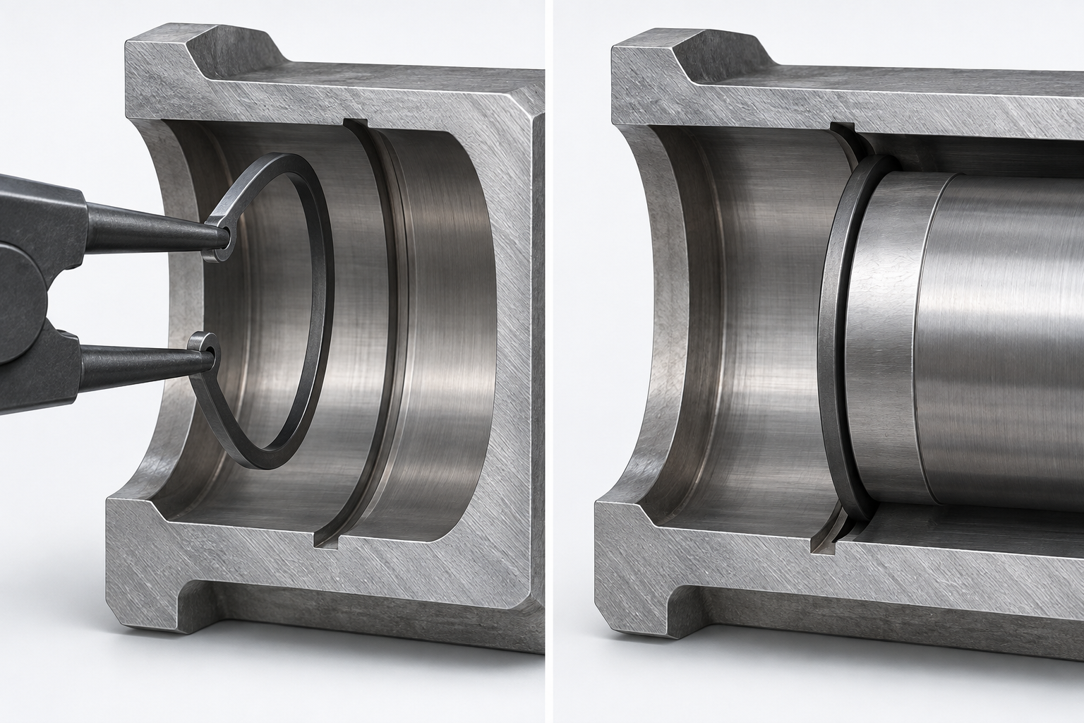
The historical reference says the ring should be contracted only as much as necessary and not below 0.99 × d1. Treat that as a DIN 472:2017-06 reference value, not an unqualified current-edition instruction. In production, the installation tool and path should minimize over-contraction, twisting and scratching while allowing the ring to seat around the complete circumference.
After assembly, verify full seating, groove cleanliness, ring accessibility and the retained component’s contact. A burr, coating buildup or large component chamfer can reduce effective support. If the ring is partly hidden, define a practical confirmation method rather than assuming that installation force proves seating.
A representative production trial is useful when the housing material, coating or installation tool changes. Use parts made to the released tolerances and record the contraction path, seating condition and any permanent deformation. Then check that the retained component bears on the intended ring face rather than on a lug, burr or groove radius. The trial confirms process compatibility; it does not replace calculation of the joint’s load capacity.
Housing material and groove edge strength are equally important. The ring may pass all incoming checks while the housing groove yields or fractures under axial load. Calculate or validate ring capacity and groove capacity separately, then use the lower value with an appropriate application safety factor.
The documentation package should trace every result to the released order. Link the drawing revision and standard edition to the material record, hardness result, finish report, dimensional inspection and production lot. If a process or material source changes, determine whether first-article evidence or requalification is needed before accepting the next lot.
TG Eugene’s DIN 472 internal-circlip product page is the relevant bore-ring sourcing route. Submit the bore and groove drawing, current standard edition, material, finish, quantity and inspection-document requirement. Final conformity should be confirmed against the approved order and production-lot evidence.
When an existing drawing states only “DIN 472,” use the quotation stage to close the missing scope. Confirm the edition, ring type, finish and document level, and verify that the bore groove was designed for the selected ring. Otherwise, two quotations may appear comparable while including different material, coating or inspection obligations.