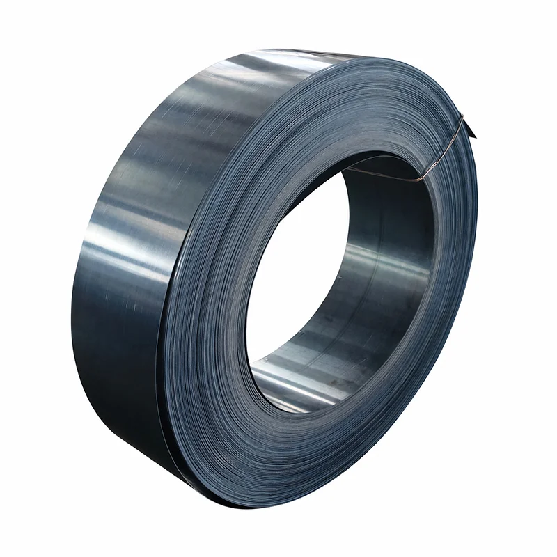
Circlip vs snap ring is not a reliable way to separate two universal product families. In industrial use, both names often describe retaining rings: removable rings that sit in a groove and form a shoulder for axial retention. “Retaining ring” is the broader functional term.
The name alone does not tell a buyer whether the ring fits a shaft or a bore, installs axially or radially, uses plier lugs, or follows a particular standard. Identify those features before selecting a catalog item or approving a replacement.
Retaining ring describes the job. The ring occupies a machined or formed groove and limits axial movement of a nearby component. Bearings, sleeves, gears, rollers, and other parts may use this removable shoulder instead of a bolted plate or a permanently formed feature.
Circlip and snap ring are common names within that category. Suppliers, engineers, and maintenance teams may prefer one term, but usage varies. A rigid rule such as “circlip means one region and snap ring means another” can create false confidence. The drawing and geometry provide better evidence.
The phrase “snap ring” can also appear in descriptions of several constructions. Some have two lugs for pliers. Others have a different section or installation method. Treat the name as a starting point for identification, not as a complete part number.
Two questions quickly narrow the field: where is the groove, and how does the ring enter it? These facts remain useful even when the original packaging or part number is missing.
| Ring form | Where it fits | Typical installation direction | Identification record |
|---|---|---|---|
| External ring | Groove on a shaft | Axially over the shaft end | Shaft diameter, groove, lugs, standard |
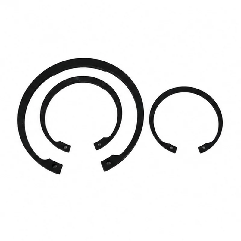
| Internal ring | Groove inside a bore or housing | Axially into the bore | Bore diameter, groove, lugs, standard |
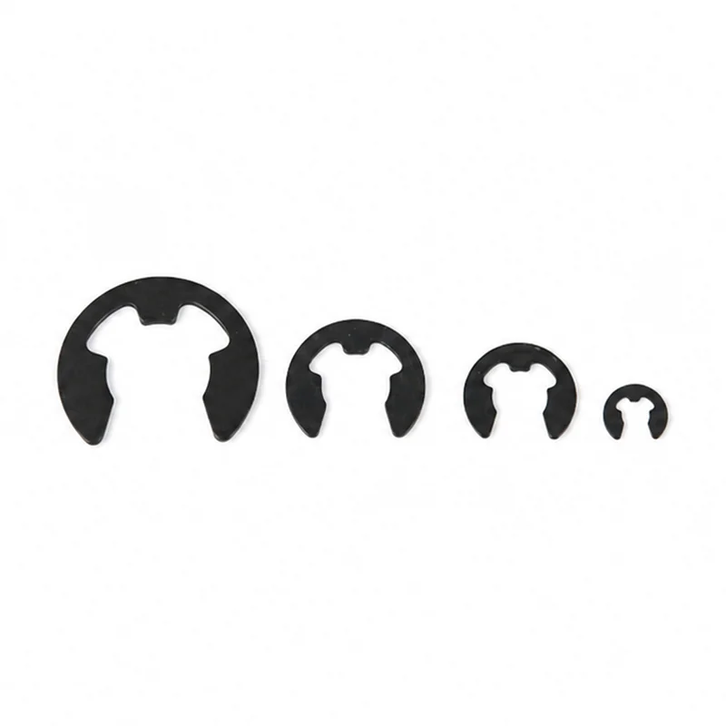
| E-type ring | External groove on a shaft or pin | Radially from the side | Shaft or groove size, access direction, standard |
An external ring usually expands during installation so it can pass over a shaft and seat in the groove. An internal ring usually contracts so it can enter a bore. An E-type ring approaches the groove from the side. These descriptions identify the assembly route; they do not establish load capacity, groove dimensions, or interchangeability.
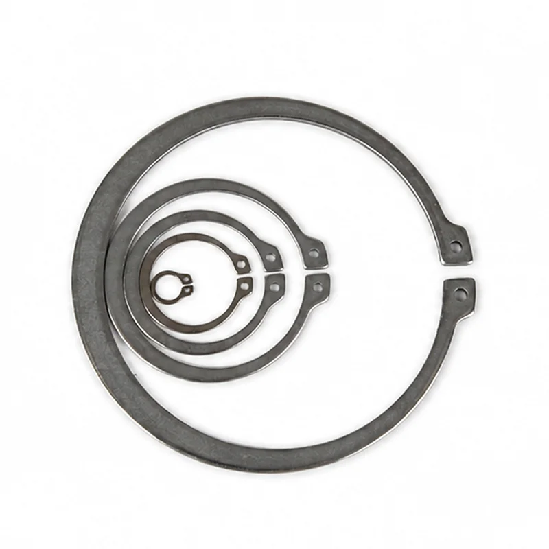
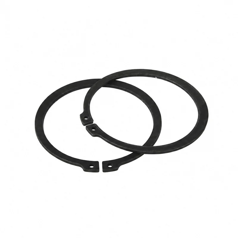
An external circlip sits in a groove around a shaft. Its outer edge creates the retaining shoulder after installation. The lugs on many designs accept retaining-ring pliers, allowing the ring to expand during assembly or removal.
Record the shaft and groove as finished features. Coating, heat treatment, grinding, and wear can affect the interface. Also check the retained component’s edge geometry and available axial clearance. A ring that enters the groove may still be wrong for the working load or assembly envelope.
When the released design specifies the German external-ring family, review the TG Eugene DIN 471 external circlip route. Match the drawing and standard before choosing a size.
An internal snap ring sits inside a housing or bore. Installers contract the ring so it can pass into the opening, then release it into the internal groove. The working shoulder faces inward toward the retained component.
Do not select an internal ring from the outside diameter of a loose sample alone. Identify the bore, groove, ring orientation, lug access, and retained component. Confirm that the installation tool can reach the lugs without twisting the ring or damaging the bore.
For a bore-mounted German-standard route, compare the released requirement with the DIN 472 internal circlip product family. The product name identifies the route, not final assembly approval.
An E-clip has an open, three-pronged profile and enters an external groove radially. This side-entry approach can help when the shaft end is blocked or when the assembly sequence favors lateral access. It also requires clear tool access at the groove.
Do not substitute an E-clip for an axially installed external ring simply because both fit an external groove. Their sections, installation methods, groove requirements, and load behavior differ. Use the governing drawing and product data.
TG Eugene lists a DIN 6799 E-type retaining-ring route for designs that call for that family.
This record allows a supplier to resolve vocabulary without guessing. It also helps maintenance teams compare an old part with the current drawing. If the sample and drawing disagree, stop and identify which configuration controls the assembly.
Keep photographs, measurements, and the approved product designation with the maintenance record. That evidence reduces the chance that a later order repeats the same naming ambiguity.
A removed ring can reveal whether the original part was external, internal, or radial-entry. It cannot prove the released groove dimensions or the ring’s original free shape. Removal, overload, corrosion, and repeated service can distort the sample.
Photograph the ring before measurement and record its installed orientation. Measure the shaft or bore and groove from the assembly drawing or controlled part features. If only a sample is available, mark every inferred value for engineering confirmation instead of turning it directly into a purchase specification.
Receiving inspection should verify the ordered ring family, designation, finish, and required documentation. Assembly validation should also confirm seating in the groove, retained-component clearance, tool access, and visible damage after installation. Use project-specific sampling and acceptance limits; the article does not provide a universal inspection plan.
State the ring type, mounting location, installation direction, governing standard, nominal designation, material or finish, and required documentation. Add the finished groove and mating dimensions controlled by the design authority. Include quantity, inspection level, packaging, and destination for quotation.
Use the snap-ring types and uses guide for a broader introduction. Keep each final part tied to its own drawing and standard. Similar names or nominal sizes do not prove that two rings share the same groove or capacity.
They often overlap in everyday use, but the terms do not guarantee identical geometry. Confirm shaft or bore location, installation direction, ring form, groove, and standard.
Usage can change by supplier, market, and industry. Avoid relying on a regional naming rule. A controlled drawing and product designation are more dependable.