When a mechanical design engineer in Stuttgart encountered a seized gearbox shaft, she opened an external circlip with undersized pliers; one tip slipped within seconds, the ring twisted, and the shaft shoulder was scored. In this realistic scenario, the quick verdict might be “bad steel.” The real causes were mismatched tool tips, poor groove access, and no service-removal plan in the original assembly.
Summary: De-energize and depressurize the machine, identify whether the part is external, internal, or E-type, and use the correct retaining ring pliers or removal tool with eye protection. DIN 471 covers circlips for shafts, while DIN 472 covers circlips for bores; neither designation alone proves that a removed part remains fit for reuse. Controlled movement, groove cleaning, and replacement of distorted parts protect the assembly better than greater hand force.
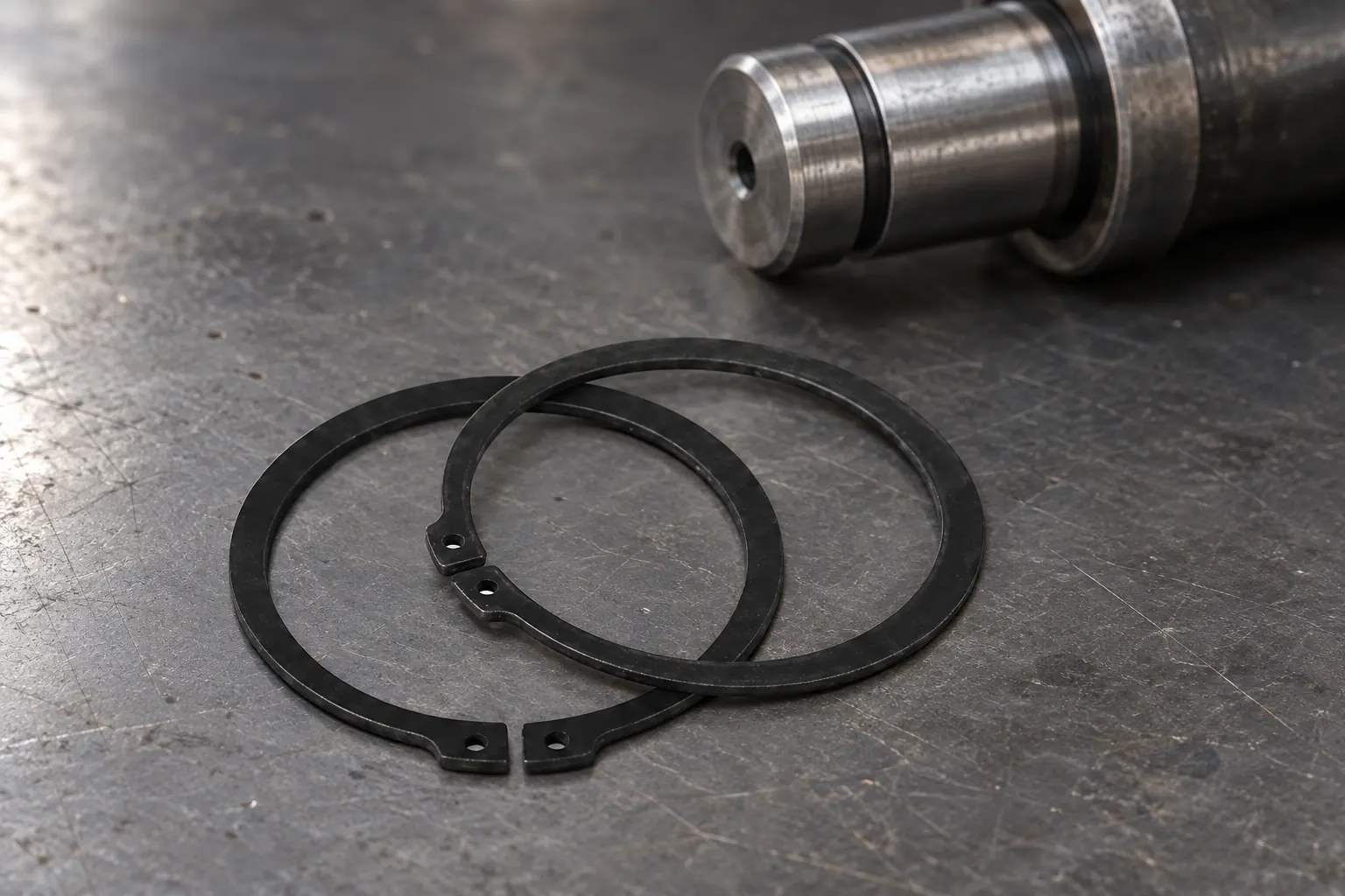
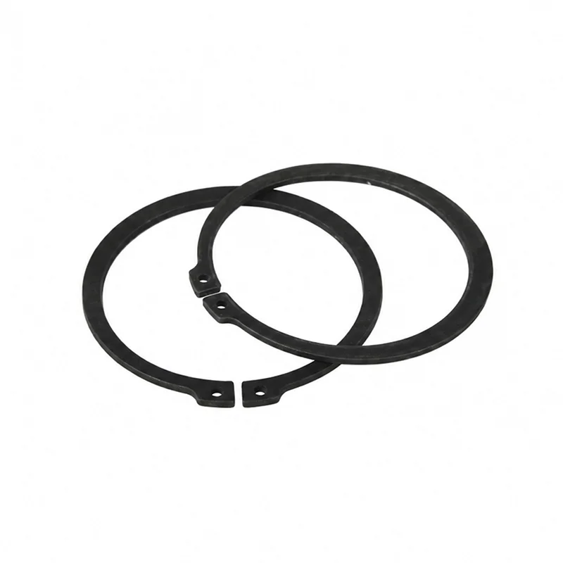
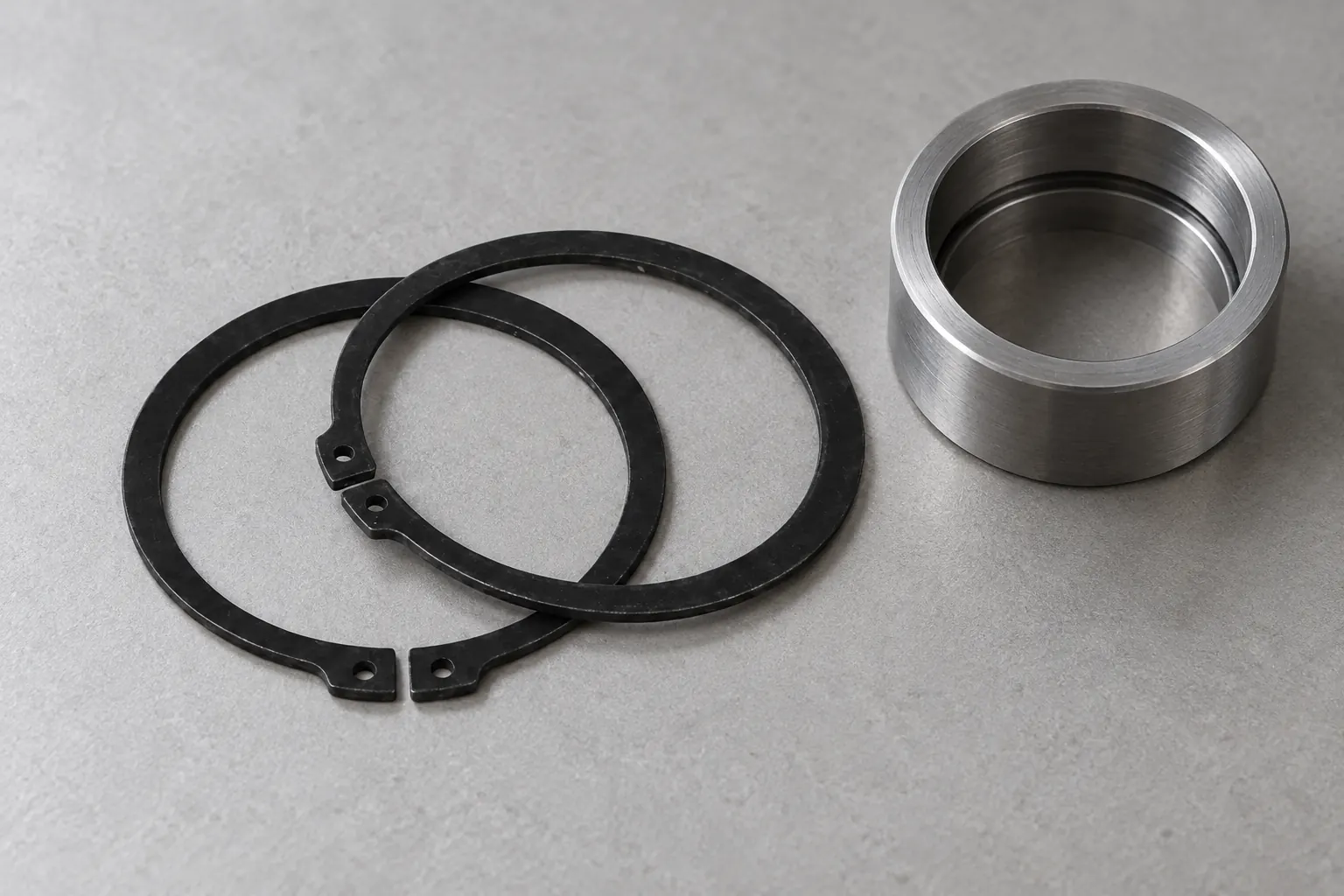
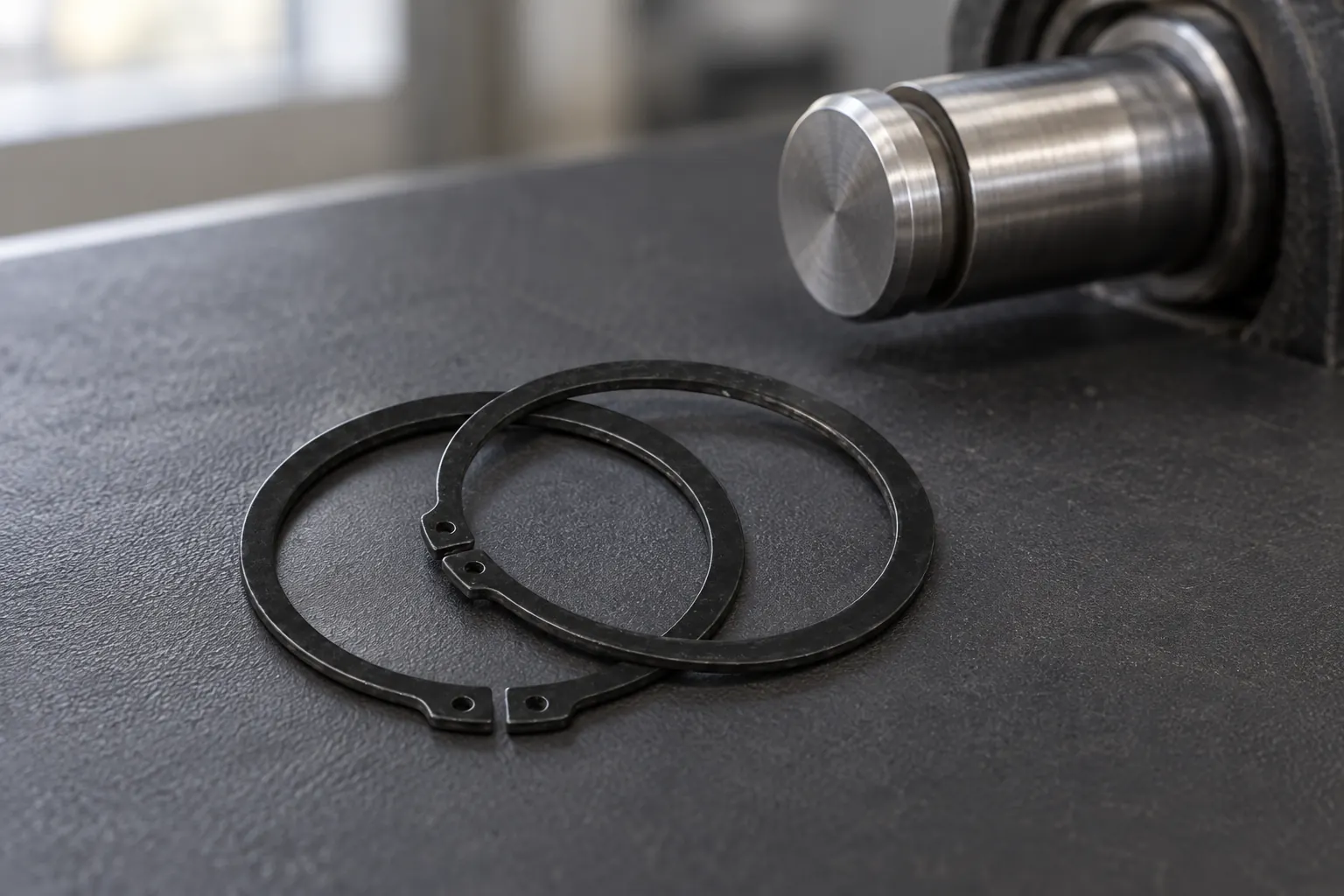
A retaining ring is a removable axial stop seated in a machined groove. External versions grip a shaft and normally open during removal; internal versions sit in a bore and normally close. An E-type part enters a radial groove from the side. Those three geometries demand different access paths, even when their nominal diameters appear similar.
Failure often begins at the interface between tool, lug, and groove. Tips that are too small can cam out of the lug holes; tips that are too large may not seat fully. Angled access adds side load, while corrosion, coating buildup, burrs, or a shoulder that blocks the tool can make a serviceable ring feel seized. The Smalley selection guide likewise treats groove design, thrust capacity, rotational speed, and installation considerations as connected decisions rather than isolated catalog fields.
Before touching the part, apply the equipment’s documented isolation procedure. Stop motion, disconnect energy sources, discharge stored electrical energy, bleed hydraulic or pneumatic pressure, support suspended loads, and verify a zero-energy state with the appropriate method. OSHA’s hand-and-power-tool guidance requires guarding and appropriate personal protective equipment; safety glasses or a face shield are particularly important because spring parts and plier tips can eject toward the operator.
Choose retaining ring pliers by ring type, lug-hole diameter, working range, tip orientation, and clearance—not by handle length alone. External jaws spread as the handles close; internal jaws compress. Straight tips suit axial access, while 45-degree or 90-degree tips can clear shoulders, provided both tips remain fully engaged and load stays symmetrical.
| Method | Best fit | Control and efficiency | Damage and TCO considerations |
|---|---|---|---|
| Dedicated external pliers | Lugged shaft circlip | Controlled, even expansion | Low damage tendency when tips fit; reusable tools reduce repeat-service time |
| Dedicated internal pliers | Lugged bore circlip | Controlled, even compression | Protects bore and groove better than prying; inspect tips regularly |
| E-clip removal tool | Radially installed E-type ring | Direct force at the open side | Limits sudden launch and shaft scratching; replacement cost is usually preferable to downtime |
| Manufacturer service fixture | High-load, guarded, or obstructed assembly | Best repeatability for production maintenance | Higher initial tool cost but lower handling variation and rework exposure |
Improvised screwdrivers are a poor choice around any energized or pressurized assembly and should never substitute for isolation. Even after isolation, prying can scratch a sealing land, notch a groove edge, or launch the part. If dedicated tooling cannot approach squarely, remove the obstructing component or use the equipment maker’s service fixture rather than forcing a diagonal bite.
Inspect retaining ring pliers before use; bent tips, loose joints, or uneven jaw movement make controlled engagement impossible.
| Ring type | Standard or form | Required action | Access check | Reuse decision |
|---|---|---|---|---|
| External shaft circlip | DIN 471 scope | Expand only enough to clear the shaft | Both lugs visible; tips aligned with shaft axis | Discard if twisted, cracked, permanently opened, or burred |
| Internal bore circlip | DIN 472 scope | Compress only enough to clear the bore | Shoulder does not block full tip seating | Discard if permanently reduced, wavy, cracked, or corroded |
| E-type circlip | Radial E-form | Drive or pull from the open side under containment | Clear radial exit path and shield the trajectory | Replace if legs spread unevenly or edges are damaged |
| Spiral or constant-section type | Manufacturer-specific form | Unwind using the specified notch or tool | Locate the removal end before lifting | Follow maker limits; do not reuse a kinked coil |
Do not reuse a distorted retaining ring, a ring that was over-expanded or over-compressed, or any part whose history and acceptance criteria are uncertain in a safety-critical joint. Visual appearance alone does not establish spring force. Follow the equipment maker’s maintenance specification; when it requires one-time replacement, treat the part as consumable.
Keep replacement retaining rings protected from corrosion and lot mixing. Do not flatten or reshape retaining rings to make them appear serviceable.
DIN numbers define dimensional and product scope, not an all-purpose certification of a supplier, batch, installation, or used component. DIN 471 applies to external circlips for shafts; DIN 472 applies to internal circlips for bores. A purchase order should still state the applicable standard edition, material, finish, dimensions, inspection documents, and any destination-market requirements. Unsupported compliance claims can cause incoming rejection, warranty disputes, and costly teardown.
Procurement should start with the groove, load case, and service sequence rather than a catalog diameter. Record whether the joint is a shaft or bore application, the groove dimensions and tolerances, axial load direction, speed, temperature, environment, mating material, finish restrictions, and expected maintenance interval. Rotor Clip’s technical materials distinguish multiple ring families; the form must match both retention duty and installation method.
For new designs, Eugene can discuss standard DIN products and custom fastener solutions with engineers and sourcing teams. Buyers can compare the company’s DIN 471 external circlip and DIN 472 internal circlip pages, then align drawings, access, material, finish, and documentation before sampling.
It is a spring fastener that sits in a groove and limits axial movement of a component on a shaft or inside a bore. Selection depends on groove geometry, load, environment, and installation access; it is not interchangeable merely because the nominal diameter matches.
Retaining rings are often called circlips, snap rings, or retaining clips, although regional and supplier terminology varies. Confirm the drawing, standard, cross-section, and installation direction rather than ordering by a nickname alone.
They provide controlled expansion or compression of lugged rings during installation and removal. Correct retaining ring pliers keep both tips engaged and reduce uncontrolled bending; the tool range and tip geometry must match the part.
An external version fits a groove on a shaft and retains a component against axial movement. A DIN 471-type part is normally expanded for removal, but only enough to pass over the shaft diameter.
The jaws move the tips together as the handles are operated, compressing the part so it can clear a bore. Both tips should be fully seated, and force should be released slowly after the part is captured.
Safe removal is a design-and-process question: isolate energy, match tool motion to ring geometry, limit deformation, contain the part, clean the groove, and apply defined inspection rules. Specifying access at the design stage avoids improvised field methods and makes maintenance time more predictable. The durable lesson is simple: protect the groove and control the spring before judging the steel.
For application-specific sizing and sourcing, review Eugene’s retaining rings portfolio and contact the engineering sales team with the drawing, groove data, service conditions, and documentation needs.