An internal snap ring size chart starts with the nominal housing or bore diameter, but that number does not describe the entire ring. You must also read the groove diameter, groove width, groove depth, ring thickness, free diameter, and the clearance details that affect seating. Treat these internal retaining ring dimensions as separate controlled fields.
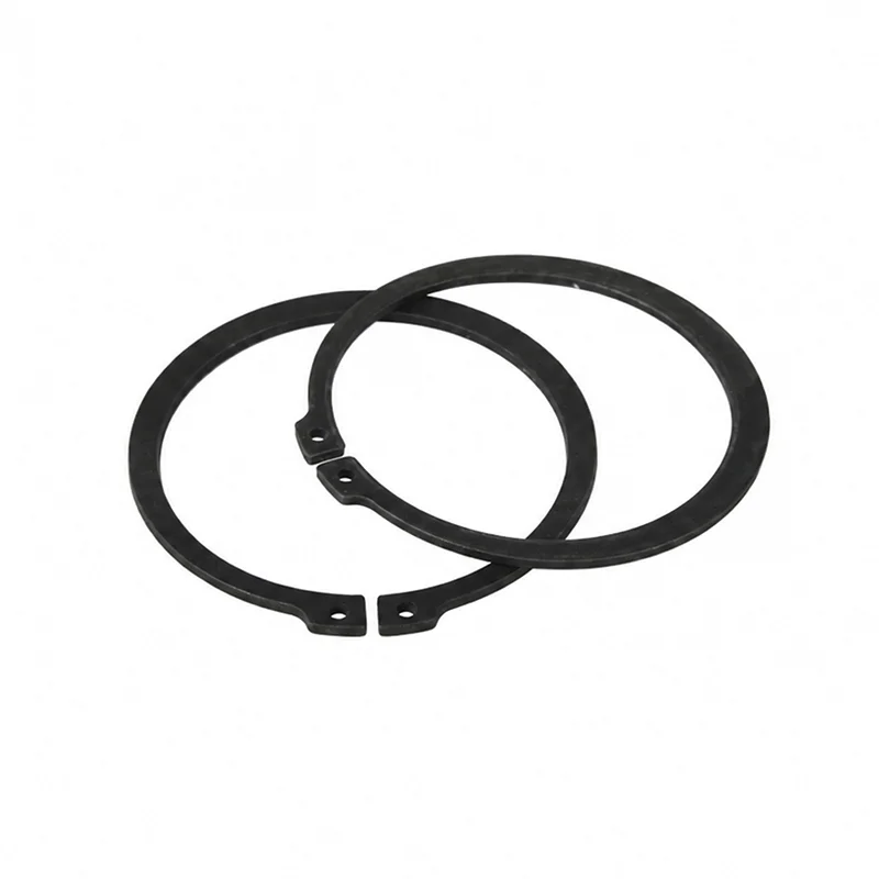
Axially installed tapered-section internal rings such as the cited DHO/DIN 472 style seat in a housing or bore groove. Their protruding shoulder limits axial movement. If you still need to separate this style from external circlips and E-rings, read what a snap ring is and how the main types differ before using a size chart.
DIN Media lists DIN 472:2026-05 as the current edition for retaining rings for bores in normal and heavy types. It replaces DIN 472:2017-06. Verify values against the current controlled standard or an approved manufacturer specification before releasing a new drawing.
Record the standard and edition beside the selected size. If a supplier chart uses different symbols, follow the legend on that chart rather than assuming that one letter always has the same meaning.
Read the chart in three groups: the housing and groove, the ring itself, and the assembly-clearance or load fields. The symbols below follow the public DHO internal-ring chart used for the worked example. Another chart may use different letters.
| Chart field | What it describes | How to use it |
|---|---|---|
| Dh — housing diameter | The nominal bore size used to identify the ring series. | Start here, but do not use it as the free ring diameter or groove diameter. |
| Dg — groove diameter | The diameter measured at the bottom of the internal groove. | Control the stated range or tolerance on the housing drawing. |
| W — groove width | The axial width available for the ring in the groove. | Compare it with ring thickness and any chart note about minimum width. |
| D — groove depth | The radial depth from the bore surface to the groove bottom. | Use the chart value with Dg and Dh; do not derive a tolerance that the chart does not provide. |
| T — ring thickness | The axial thickness of the ring section. | Use its allowed range when checking seating and groove-width clearance. |
| Df — free diameter | The ring diameter before installation. | Do not confuse it with nominal bore size. An internal ring normally compresses during installation. |
| H, S, R — lug and section fields | Lug height, radial section, and plier-hole diameter in the cited chart. | Use them to review tool access and surrounding clearance, not to replace the groove callout. |
| Y — minimum edge margin | The material distance from the groove area to the housing edge. | Check that the housing layout provides at least the listed margin. |
| R/Ch — radius or chamfer limit | The allowable corner radius or chamfer shown by the chart. | Control this detail where the retained component bears against the ring shoulder. |
| Pr, Pg — published thrust-load fields | Separate ring and groove values under the source’s stated conditions. | Do not select a ring from these numbers until material, geometry, safety factors, and source conditions match the application. |
Rotor Clip’s public DHO-15 product page provides a useful reading example. It lists a 15.000 mm housing diameter, but the groove diameter is 15.700–15.810 mm and the free ring diameter is 16.100–16.560 mm. These are three different dimensions for one nominal size.
| Field | Published DHO-15 value | Reading purpose |
|---|---|---|
| Dh | 15.000 mm | Nominal housing size |
| Dg | 15.700–15.810 mm | Groove-bottom diameter |
| W | 1.100 mm | Groove width |
| D | 0.350 mm | Groove depth |
| Df | 16.100–16.560 mm | Free ring diameter |
| T* | 0.940–1.000 mm | Base-listed ring thickness |
| Y min. | 1.100 mm | Minimum edge margin |
| R/Ch max. | 0.500 mm | Corner radius or chamfer limit |
*The source adds 0.05 mm to the listed maximum thickness for plated rings. This row teaches the relationship between columns; it is not a TG Eugene dimensional table and should not be copied to another size. Release dimensions from the current standard, the selected manufacturer’s controlled specification, and the approved application drawing.
Actual measurements can help compare an unknown part with a chart, but they do not replace its nominal specification. Record the ring and the housing as separate sets of fields.
A clear handoff separates the part requirement from the groove and from the operating conditions. The following matrix is a practical review aid, not a replacement for the applicable standard or an engineering load calculation.
| Decision group | Fields to control | Why it matters |
|---|---|---|
| Ring identity | Internal ring type, DIN 472 edition, normal or heavy type, nominal bore size | Prevents a similar-looking ring family from being substituted. |
| Housing groove | Bore diameter, groove diameter, width, depth, location, edge margin, radius/chamfer | Controls where the ring seats and how much shoulder remains exposed. |
| Ring order | Material, finish, quantity, packaging, and any drawing-controlled dimensions | Keeps purchasing fields separate from assumptions based on a generic chart. |
| Application | Retained component, axial load case, environment, assembly method, and available tool clearance | Shows where a standard size check ends and application review begins. |
| Inspection | Characteristics to verify, sampling or inspection requirement, and required records | Defines how the delivered part and machined groove will be accepted. |
When these inputs are controlled, buyers can review the TG Eugene DIN 472 internal circlip product route against the actual drawing. Send the standard edition, bore and groove details, material and finish requirement, quantity, and inspection needs together.
No. The nominal size normally identifies the housing or bore. The free diameter describes the relaxed ring before installation and is a separate chart field.
An edition date removes ambiguity when tables or references change. For new work, verify the current controlled standard and record the edition used for the selected dimensions.