 Wenzhou Eugene Technology Co., Ltd.
 Summary: A retaining ring should be selected from the shaft-and-groove interface, not nominal diameter by itself. DIN 471 identifies a standard family for external retaining rings used in shaft grooves, while ISO 286-1 provides the language for dimensional tolerances; neither replaces application engineering. The practical action is to document shaft diameter, groove dimensions, ring designation, material/finish needs, load direction, and installation method on the drawing and purchase specification before sourcing.
What dimensions define a shaft lock ring interface?
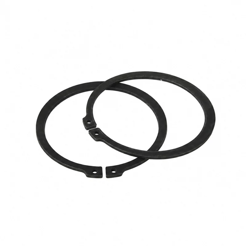
A retaining ring is a spring-steel component that transmits axial restraint by seating in a groove and bearing against an assembled part. The component therefore has two interfaces to manage: its engagement with the groove and its contact with the retained component. For an external ring on a shaft, the nominal shaft size is only the starting point. Groove diameter, groove width, corner form, available shoulder, shaft tolerance, burr condition, and the lock ring’s free-state geometry all affect whether the ring can seat and retain as intended.
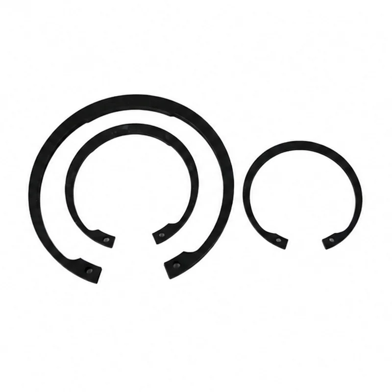
DIN 471 is commonly used to identify external circlips for shafts; DIN 472 addresses internal circlips for bores. They describe dimensional standard families and should be read with the applicable edition and the product drawing, rather than treated as a universal guarantee of installed performance. ISO 286-1, the ISO system for limits and fits, helps engineering teams state the shaft tolerance that accompanies the groove. That distinction matters because an apparently matching ring can still be unsuitable where the groove or shaft condition falls outside the selected interface assumptions.
Which drawing details prevent an ambiguous order?
A usable callout identifies the relevant DIN family or an approved custom drawing, nominal shaft diameter, groove diameter and width, groove edge condition, material/finish expectation, and revision status. It should also state whether the ring retains a rotating, stationary, shock-loaded, or reversibly loaded component. NASA’s Fastener Design Manual is useful general design guidance on joint and loading considerations, but it is not a retaining-ring product certification or a substitute for an application-specific calculation.
Why do assembly details belong in the specification?
Installation pliers, access around the shaft, required expansion, and inspection visibility can change the practical choice even when dimensions appear equivalent on paper. A lock ring distorted during installation may not seat fully; a groove obscured by adjacent parts may make visual confirmation unreliable. The drawing or work instruction should define the approved installation method and a seating check appropriate to the assembly.
How should shaft lock ring alternatives be compared?
Comparison should begin with the load path and assembly environment, then extend to total cost of ownership. The lowest apparent unit-cost option can add cost through drawing clarification, extra inspection, assembly rework, line interruption, or returned assemblies. The following comparison is qualitative; it is not a price list or a performance rating.
| Option | Performance focus | Compatibility question | Unit-cost tendency | Maintenance and return-risk drivers | TCO implication |
|---|---|---|---|---|---|
| DIN 471 external circlip | Axial retention on a grooved shaft | Does the shaft groove match the selected standard family? | Often economical for standardized interfaces | Groove variation, incomplete seating, installation damage | Favorable when the interface and inspection method are controlled |
| DIN 472 internal circlip | Axial retention in a grooved bore | Is the retention feature in a bore rather than on a shaft? | Application dependent | Wrong-side selection, bore access, seating verification | Not interchangeable with a shaft-ring solution |
| Custom retaining feature | Accommodation of nonstandard geometry or loading | Can drawings, validation, and supply controls be maintained? | May increase with development and documentation | Revision control, validation scope, sourcing continuity | Can reduce risk where a standard interface does not fit the design |
For an illustrative TCO review, a buyer can compare not only quoted part cost but also drawing-review time, incoming checks, assembly labor, expected rework path, and the administrative cost of a nonconforming shipment. The calculation should use the organization’s own rates and failure history. ISO 14253-1 is relevant to the broader inspection conversation because it sets decision rules for proving conformance or nonconformance with specifications, including how measurement uncertainty is considered.
How does shaft lock ring for dimensions guide groove selection?
The phrase shaft lock ring for dimensions is best approached as a checklist, not a single catalogue field. First identify the shaft and selected ring family; then use the governing drawing or current dimensional table to specify groove diameter, width, edge profile, and allowable variation. Do not copy groove dimensions from a visually similar bore ring or from an uncontrolled secondary source. DIN 471 and DIN 472 separate external-shaft and internal-bore applications, so the location of the groove is a primary decision.
| Application condition | Shaft and groove data to confirm | Ring-family direction | Assembly check | Specification action |
|---|---|---|---|---|
| Standard external shaft retention | Nominal shaft diameter, groove diameter, groove width, shaft tolerance | Evaluate DIN 471 external circlip dimensions | Confirm full seating around the groove | Reference the applicable DIN 471 designation and drawing revision |
| Internal retention in a housing bore | Bore diameter, bore groove dimensions, access depth, retained-part shoulder | Evaluate DIN 472 internal circlip dimensions | Confirm seating within the bore | Keep bore-ring details separate from the shaft requirement |
| Restricted tool access or automation | Clearance for tool jaws, insertion path, visual/fixture access | Choose a form factor compatible with the process | Use a defined fixture or inspection step | Add assembly method and acceptance criteria to the work instruction |
| Corrosive or variable service environment | Base material, finish, exposure definition, storage/handling needs | Confirm material and finish against service needs | Inspect coating condition without damaging the ring | State the required evaluation method when corrosion performance is claimed |
When dimensional information is incomplete, procurement should ask for the mating-part drawing and the intended standard edition before comparing quotations. A correct nominal diameter cannot compensate for an unspecified groove. The resulting record should permit incoming inspection to distinguish a wrong part from a correct part installed in a nonconforming interface.
Which standards matter when specifying a shaft lock ring?
Standards should be used according to scope. DIN 471 is the dimensional reference family for external retaining rings on shafts; DIN 472 is the corresponding internal-ring family for bores. ISO 286-1 provides limits-and-fits terminology for the mating feature. These references help a buyer request a coherent interface, but they do not certify the suitability of a given ring for every load case, material, coating, or installation process.
ISO 14253-1 concerns decision rules in verification of geometrical product specifications, making it relevant where measurement uncertainty affects an acceptance decision. ISO 9227 specifies salt-spray testing for corrosion testing of metallic materials and coatings; it is a test method, not a blanket durability certification. A buyer should request a named method, exposure condition, acceptance criterion, and sample basis only when corrosion performance is genuinely required. Claims that a ring is “compliant” or “certified” without identifying the applicable product, market, and evidence can create commercial disputes, rejected documentation, or unsuitable substitutions.
How can buyers select a shaft lock ring for machinery?
For machinery programs, the procurement sequence should be deliberate:
- Start from the function: identify axial load direction, retained-component geometry, vibration or shock exposure, and any service environment that affects material or finish.
- Freeze the mating interface: place controlled shaft and groove dimensions, tolerance references, and revision data on the engineering drawing.
- Match the family to the location: separate an external DIN 471 shaft solution from a DIN 472 bore solution and verify installation access.
- Define evidence: agree on dimensional records, visual seating criteria, traceability needs, and any genuinely applicable test method before order release.
- Qualify the supply path: compare samples or first articles against the controlled interface and document deviations before production use.
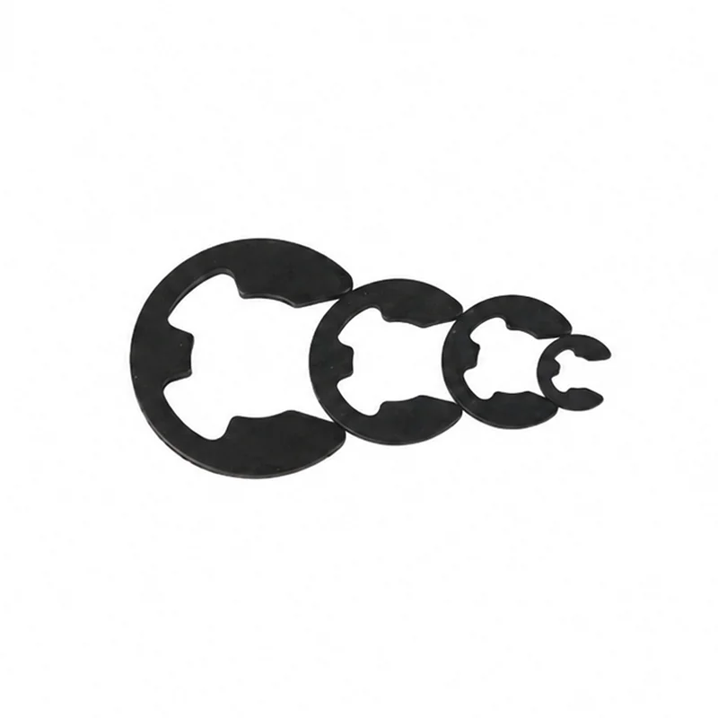
For buyers seeking configurable circlips and custom fasteners, Eugene can support a drawing-led discussion of form, material, finish, and sourcing documentation. Its shaft lock ring range is a useful starting point for identifying relevant retaining-ring forms; engineers should still confirm final fit against the designated groove and application. A DIN 471 product page can help procurement distinguish the external standard family from other circlip forms, while an E-type alternative may suit a different interface or assembly constraint.
How do these shaft lock ring questions guide procurement?
What is the difference between a shaft retaining ring and a bore retaining ring?
A shaft retaining ring engages a groove machined on the outside of a shaft, while a bore retaining ring engages a groove inside a housing or bore. DIN 471 is associated with external shaft rings and DIN 472 with internal bore rings. The mating feature, not a similar nominal diameter, determines which family should be evaluated.
Is DIN 471 a performance certification?
No. DIN 471 is used as a dimensional standard family for external retaining rings; it does not by itself certify every installed application. The buyer should pair the relevant designation with the actual groove drawing, material/finish requirements, and any validated load or assembly criteria.
What should be measured during incoming inspection?
Inspection should reflect the controlled purchase specification and may include ring identity, relevant free-state dimensions, condition, and documentation, plus confirmation that the mating shaft/groove is controlled separately. ISO 14253-1 is helpful where measurement uncertainty needs a defined acceptance decision. The inspection plan should not imply that a component check alone proves installed retention.
Can an E-type circlip replace a standard external circlip?
Not automatically. E-type and external circlips can have different groove engagement, installation behavior, and retained-part geometry. Compare the governing drawings and function first; see this DIN 6799 E-type circlip example for form-factor context.
Where can a team learn the basic snap-ring terminology?
A concise snap-ring overview can align engineering and purchasing vocabulary before a drawing review. It should complement, not replace, the controlled product specification for the assembly at hand.
Which sources support shaft lock ring specification work?
- ISO 286-1, ISO system for limits and fits.
- ISO 14253-1, decision rules for verification of geometrical product specifications.
- ISO 9227, salt spray tests for corrosion testing of metallic materials and coatings.
- NASA Fastener Design Manual, general design guidance rather than product certification.
For machinery manufacturers, the selection discussion should also be connected to the wider machinery-manufacturing application context, including assembly controls and service conditions.
The durable lesson is simple: nominal diameter starts the conversation, while controlled mating dimensions, installation, and evidence finish it. At the decision point, Eugene’s circlips category can help a team compare suitable retaining-ring forms and begin a drawing-based enquiry. Contact its technical sales team with the shaft, groove, and application details needed for a focused review.