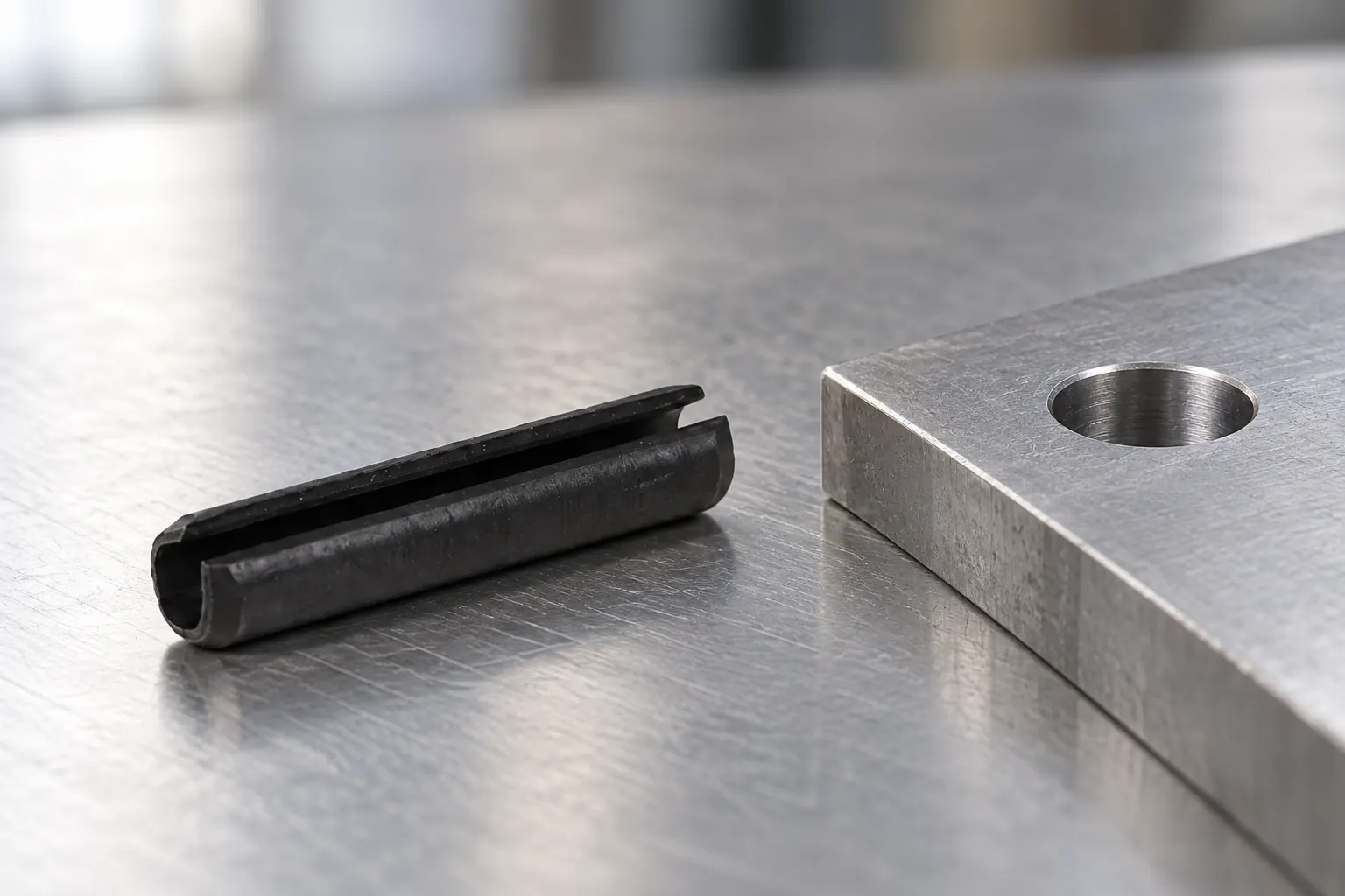
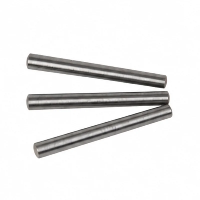
Dowel pin sizes are normally identified by nominal diameter and nominal length. Those two values describe the basic pin, but they do not complete a controlled purchase specification. A controlled order should identify the governing standard or drawing, pin tolerance and receiving-hole requirements. It should also state material, finish and removal features when the selected standard or application does not already control them.
This distinction matters for metal locating pins. A diameter listed in a catalog is not automatically the hole size, and one fit cannot be applied to every assembly. The drawing should state which component retains the pin, how the mating component locates, and which dimensions inspection must verify.
A basic dowel-pin callout uses nominal diameter × nominal length. For example, the first value identifies the nominal pin diameter and the second identifies the nominal length defined by the selected standard or drawing. The callout should use one unit system consistently.
Nominal diameter is the size designation. Nominal diameter does not replace the permitted pin-diameter tolerance. The actual manufactured diameter must stay inside the tolerance assigned by the applicable standard or approved drawing. That tolerance affects the receiving-hole decision.
Length also needs a clear definition. End geometry can change where measurement begins and ends, especially when a pin has rounded ends, chamfers, a thread, or another extraction feature. A purchase document should cite the standard and drawing instead of asking the supplier to infer the measurement method from a short description.
The phrase standard pin sizes therefore means sizes available within a named product standard or supplier series. It does not mean that every solid locating pin shares one universal diameter, length, tolerance or end form.
A useful size chart must match the intended pin family. ISO 2338 covers parallel pins made from unhardened steel and austenitic stainless steel. ISO 8734 covers hardened-steel and martensitic-stainless parallel dowel pins. The selected parallel pin standard affects more than the material description, so its number belongs on the drawing or purchase order.
Internal threads create another branch. ISO 8733 covers unhardened parallel pins with internal thread, while ISO 8735 covers hardened versions. The thread provides an extraction interface; it should not be added as a generic note after the body size has already been selected.
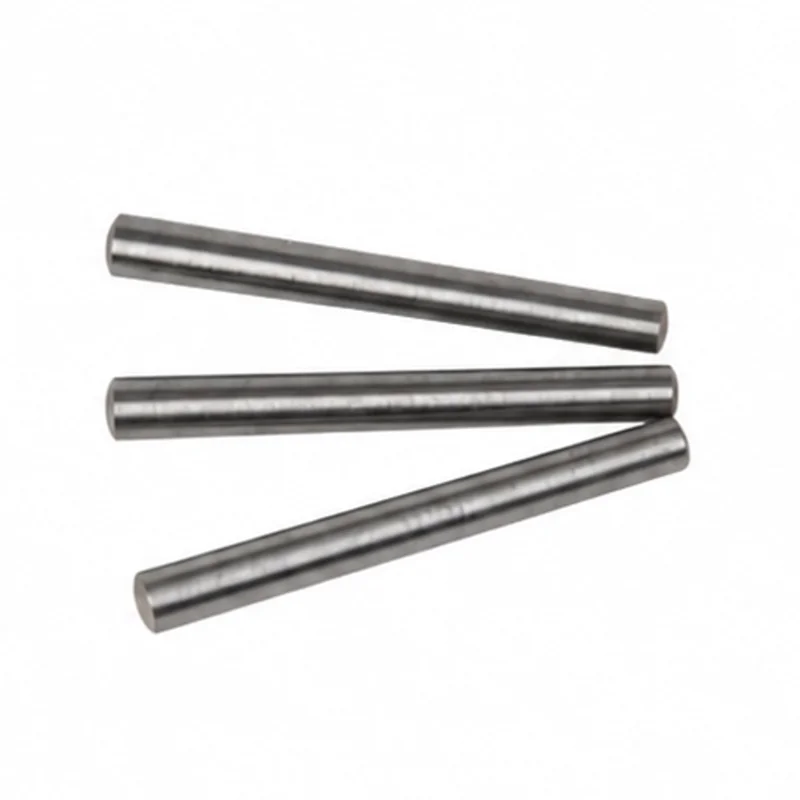
TG Eugene’s DIN1 cylindrical dowel pin is one plain, unhardened product route. Its product record identifies a ground 40Cr cylindrical pin with a bright finish. Use its approved product drawing to confirm available dimensions and tolerances rather than transferring values from an unrelated chart.
Consider two drawings that call for the same nominal diameter and length. The first uses a plain pin in a location with through access and no threaded extraction requirement. DIN1 is the relevant TG Eugene product route to review. The second drawing requires later extraction from a blind or deep location. DIN7978 is the relevant route because its internal thread provides an extraction interface.
This example does not make the two products dimensionally interchangeable. The buyer must confirm that the required diameter, length, thread detail and tolerance appear on the selected product drawing. The service requirement chooses the product route; the approved drawing controls the final size and fit.
The required dowel pin fit begins with the joint function. Identify the component that permanently or repeatedly retains the pin. Then identify the mating component that must assemble over the pin, locate against it, or be removed during service. These two holes may perform different jobs and should not receive copied tolerances without review.
Pin tolerance and hole tolerance form one dimensional system. Their worst-case limits determine whether the resulting condition is interference, transition or clearance. The host material, coating, wall thickness and hole-making process can also affect assembly behavior. Engineering should release the final limits after checking these conditions.
Hole preparation belongs in the same discussion. A drilled hole, reamed hole and finished bore do not automatically produce the same size control, roundness or surface condition. The drawing should define the finished hole requirement that inspection will accept. It should also identify whether the hole is blind or through and provide a usable depth where that affects installation.
Avoid using one online drill-size value as a universal dowel pin hole tolerance. A published recommendation may apply to a different pin type, tolerance class, host material or retention method. Use the selected standard and supplier data as inputs, then place the approved pin and hole limits on the controlled drawing.
Hardened and unhardened pins are separate specification choices. Neither term is complete without the material standard and required condition. If hardness matters, state the approved range and test method on the drawing or purchase specification. Do not rely on a product-family name to carry that requirement.
Surface finish also needs a purpose and an exact requirement. A bright ground surface describes appearance and processing, but it does not by itself establish corrosion resistance, friction or service life. Coating or passivation requirements should name the applicable specification and include any dimensional allowance that affects the fit.
Plan removal before selecting the end form. A plain pin may suit an accessible through-hole, while a blind or serviceable location may need an extraction feature. TG Eugene’s DIN7978 internal-thread dowel pin shows one such product route, with an internal thread at one end. The thread size, usable engagement and extraction access still need confirmation from the approved drawing.
The following framework keeps a request for quote focused on the information a supplier and buyer must align. The framework is a purchasing checklist, not a replacement for the selected product standard.
| Field | What to state | Why it matters |
|---|---|---|
| 1. Pin family and standard | Parallel, internally threaded or another approved type; standard number and revision | Locks the applicable geometry, condition and inspection basis |
| 2. Nominal diameter | Diameter designation and unit | Identifies the basic pin size without pretending it is the hole size |
| 3. Nominal length | Length designation and measurement basis | Prevents ambiguity around ends, chamfers and threaded features |
| 4. Pin tolerance and condition | Applicable tolerance class, heat-treatment condition and inspection requirement | Controls the actual pin delivered inside the nominal designation |
| 5. Receiving-hole requirements | Function of each hole, finished size and tolerance, depth and process notes where needed | Defines retention, assembly and location as one controlled system |
| 6. Material and finish | Material grade, required hardness when applicable, coating or surface condition | Prevents a generic material description from replacing measurable requirements |
| 7. End and removal feature | Plain, rounded, chamfered or internally threaded end as shown on the drawing | Connects installation and service access to the selected product |
Inspection should follow the same characteristics used to place the order. Mark each feature that requires a report, identify the accepted measuring method, and define any sampling agreement before production. This prevents a supplier’s catalog description from becoming the acceptance standard by default.
A complete dowel-pin specification lets the supplier quote the intended part and lets inspection verify the same requirement. Diameter and length remain the starting point. The standard, pin condition, hole function and removal plan make the order controllable.