A round wire retaining ring is formed from wire with a circular cross-section and sits in a machined groove. External versions retain parts on a shaft. Internal versions retain parts inside a bore or housing. The two arrangements need different rings, grooves, installation access, and drawing callouts.
Round-wire rings should not be selected by overall diameter alone. Start with the retention direction, then define the groove, mating component, installation method, and expected axial movement. A familiar family name is not a complete specification.
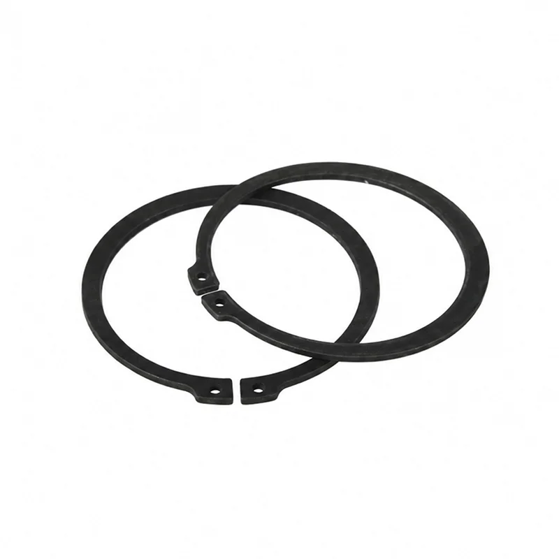
The circular wire section distinguishes this family from many stamped retaining rings, which usually have a flat section and may include lugs or holes for pliers. A round-wire ring creates a removable shoulder when part of its section projects from a groove.
The terms round wire snap ring, wire retaining ring, and wire snap ring may appear in catalogues and search results. Use geometry and installation location to identify the component. Terminology alone does not show whether the ring belongs on a shaft or inside a bore.
The retained component bears against that exposed section. The groove supports the ring. The shaft or housing, groove edges, mating component, and ring therefore work as one system.
| Arrangement | Ring location | What it retains | Drawing focus |
|---|---|---|---|
| External ring | Groove on a shaft | A component moving along the outside of the shaft | Shaft and groove diameters, groove width, shoulder contact, end access |
| Internal ring | Groove inside a bore or housing | A component moving inside the bore | Bore and groove diameters, groove width, housing wall, insertion access |
DIN 7993 Type A is commonly associated with an external shaft arrangement, while Type B is associated with an internal bore arrangement. Verify the current standard and selected product data. Catalogue family letters are not a universal drawing language.
The groove must locate the ring and support the axial load transferred by the retained component. A drawing normally needs more than one diameter. It should identify the reference surfaces and the dimensions that control the ring’s seated position.
Do not copy a groove from a visually similar ring. Match the groove to the exact ring standard and size. If the assembly uses a nonstandard groove or limited wall thickness, the designer should review the arrangement before release.
The retained component transfers axial force into the exposed ring section. The ring then transfers that force into the groove wall. Review the contact face, groove support, shaft or housing strength, and the direction of the expected force as one load path.
Reversing the load direction can move contact to another groove edge or mating surface. Shock, vibration, rotation, and repeated service may add conditions that a static layout does not show. Record these conditions for engineering review instead of relying on a generic catalogue illustration.
Keep the ring, groove, and mating part under one controlled drawing revision.
If the retained part can tilt, inspect where its edge will meet the wire section. Uneven contact can concentrate load and interfere with seating. A controlled chamfer, shoulder, spacer, or guide may be needed, but the assembly drawing must define the accepted geometry.
The exposed portion must provide the shoulder intended by the design while the groove retains enough of the section to support the ring. This balance is controlled by the exact ring and groove geometry. It cannot be reduced to one universal percentage.
Check the approved ring drawing or standard for the selected size. Also review the mating part’s chamfer and contact face. A large entry chamfer can reduce useful contact, while a sharp or damaged edge can create uneven loading.
An external round-wire ring needs a route over the shaft end or into the groove. An internal ring needs access through the housing opening. The assembly sequence should avoid stretching, compressing, or twisting the ring beyond the controlled installation method.
Before releasing the drawing, check these practical questions:
Inspect the ring around its full circumference. Look for a section that remains above the intended seated position, a twisted end, a damaged groove, trapped debris, or tool marks. Check the retained component for correct axial location and free movement where the design requires clearance.
Visual inspection alone may not verify every dimensional requirement. Use the drawing’s specified gauges or measurements for groove diameter, groove width, location, and assembly position.
Record any seating gap, damaged end, or groove defect before disassembly. A photograph can support the inspection record, but the accepted drawing and measured results should control the disposition.
Cross-section is only one part of the choice. Stamped rings may offer features for plier installation and a different contact profile. Round-wire rings can suit compact grooves and simple circular geometry. Neither family is universally better.
Compare available radial space, axial load path, groove manufacturing, installation access, service method, standard availability, and the mating component. The guide to snap-ring types and uses provides broader terminology for this comparison.
| Required input | Reason |
|---|---|
| External shaft or internal bore | Determines the basic ring orientation. |
| Standard, type and size | Prevents selection by family name alone. |
| Groove dimensions and tolerances | Controls seating, projection and support. |
| Mating-part geometry | Defines the contact shoulder and available clearance. |
| Material, finish and environment | Supports a controlled corrosion and service review. |
| Installation and removal access | Confirms that the ring can be assembled and serviced. |
| Inspection and documentation | Defines how the delivered and assembled result will be accepted. |
TG Eugene’s product catalogue can be used to browse current fastening and spring categories. This article does not state that a round-wire retaining-ring SKU is currently available. Confirm the exact ring type and drawing with the supplier before ordering.
A round-wire ring is one retaining-ring form. “Snap ring” is a broad term that can also describe stamped external, internal, E-type, and other designs.
Type A is commonly associated with an external shaft arrangement, while Type B is associated with an internal bore or housing arrangement. Verify the current standard and selected product data.
No. Use the exact ring’s approved dimensional data. Groove diameter, width, edge geometry, location, mating-part contact, and installation access all matter.