Grooved pins are solid press-fit pins with raised longitudinal ridges that engage the wall of a receiving hole. The pin body is smaller than the ridge diameter. A correctly selected hole clears the body but interferes with the raised grooves, so retention is created where those ridges contact and displace the host material.
This is different from forcing an oversized smooth dowel into an undersized hole, and it is different from compressing a hollow spring pin. For press fit grooved pins, the pin, hole, host material and installation process must be specified as one system. Copying a dowel-pin fit or a spring-pin hole range onto a grooved-pin drawing can produce excessive insertion force, weak retention or damaged parts.
The grooves are formed along part or all of the pin length. Forming the grooves raises material above the original cylindrical body. During installation, the raised crests meet the hole wall first. The body can remain below the hole diameter, which reduces the amount of metal that must be displaced compared with an oversized smooth pin.
The amount and location of the raised material depend on the selected groove pattern. Full-length grooves can create retention along much of the engagement. Partial grooves can place retention in one member while allowing the other member to rotate, slide or be located differently. This function must come from the chosen pin series and drawing; “groove pin” is not a complete geometry callout.
| Pin family | How retention is produced | Hole implication |
|---|---|---|
| Grooved pin | Raised longitudinal ridges interfere with and displace host material. | Hole clears the body but engages the groove crests; use the selected series recommendation. |
| Ground dowel | Smooth cylindrical surface uses a controlled interference or transition fit. | Tighter dimensional control and a precise hole may be required. |
| Spring pin | Hollow pin compresses and applies radial spring force against the hole. | Hole range follows the selected slotted or coiled spring-pin specification. |
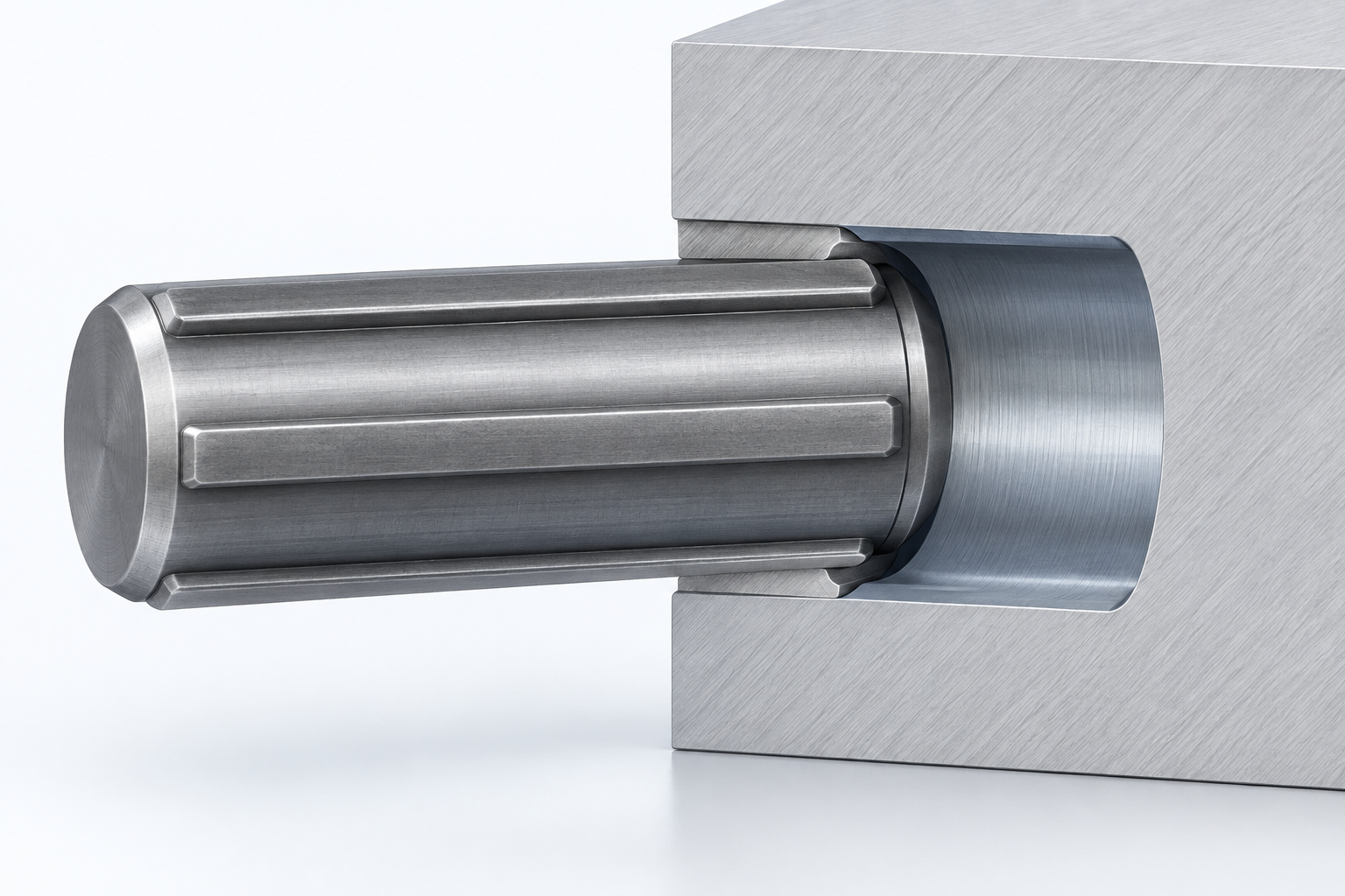
A quality drilled hole is often suitable for grooved pins, but “drilled” does not mean uncontrolled. Drill size, tool wear, runout, material, burr formation and entry condition all affect the resulting hole. The drawing should specify the finished hole requirement, while the manufacturing plan chooses the drilling, reaming or secondary operation needed to hold it.
Start with the pin supplier’s recommended hole range for the exact groove type and nominal size. Then evaluate the host. A soft aluminum casting, a thin steel wall and a hardened component will not respond to displaced material in the same way. Harder hosts can raise insertion force or limit material displacement. Softer hosts can accept the grooves more readily but may require more attention to wall thickness, edge distance and pull-out performance.
Check the hole entrance as well. A controlled lead-in helps the pin start without shaving the ridge or rolling a burr into the joint. An oversized or deep chamfer can reduce the effective engagement near the entry. A sharp, burred edge can damage the pin finish, increase insertion force and prevent the assembly from seating against its intended datum.
For a blind hole, provide room for displaced material, trapped air, oil or debris. Also define the insertion depth so the pin does not bottom before the joint closes. Through holes simplify visual confirmation and removal, but the exit edge still needs control if breakthrough burrs could interfere with assembly or adjacent parts.
The question is not simply “Which diameter?” It is “Where must the pin hold, where may it move, and how will the joint be assembled?” If the pin must remain fixed in one component while another member pivots, the groove location and engagement length should support that division. If both members must be locked, the retention zones and insertion direction need to suit both holes.
A grooved pin should be selected from the function of the joint, not from diameter alone. Consider these variables before choosing a part:
A smooth dowel remains the stronger choice when precise location and repeatable fit are the main tasks. A spring pin may fit better when a resilient pin must accommodate a broader production hole range. Grooved pins are attractive when the raised ridges can create reliable retention in a comparatively economical prepared hole, but the application still needs testing.
Press the pin along its axis with the workpiece supported close to the hole. Misalignment can score the hole, bend the pin or create a false high-force reading. A hard hammer blow makes the process difficult to monitor and can damage the lead-in; a controlled press or installation tool is easier to validate.
Track force versus travel during trials when retention is important. A sudden peak near the entrance can indicate a burr, insufficient lead-in or excessive interference. Low force throughout the stroke can indicate an oversized hole, undersized groove crests or a host material that is not engaging as expected. The acceptable window must be established from samples and the actual production materials.
Do not judge the joint only by whether the pin went in. Inspect seating depth, part distortion, cracks, raised burrs and movement after assembly. Where pull-out or torque retention is a design requirement, validate that property using the real hole process, material condition and engagement length.
TG Eugene’s pin product family provides context for related pin types. Because the current verified catalog does not identify a specific grooved-pin series, submit the required groove form, host material, hole and joint function for capability confirmation rather than assuming a listed stock part.