A constant section retaining ring has a substantially uniform radial cross-section around its circumference. The term describes geometry, not a complete part specification. It does not establish whether the ring fits a shaft or bore, which groove it needs or how much thrust it can retain. It also does not prove speed suitability or interchangeability with a tapered circlip or spiral ring.
For selection, start with the assembly location and load path. Then review groove geometry, radial space, retained-part contact, installation stress, rotation, environment and service access against the controlled data for the exact supplier series. A family name is useful for narrowing the options; it is not enough to release a drawing.
The profile remains broadly uniform in radial width rather than tapering from a wider back toward lug ends. Many constant-section designs are also lug-free. This creates a different envelope and contact pattern from a familiar axial circlip with plier holes, but the words “constant section” do not guarantee one universal opening, end geometry or installation method.
An external configuration sits in a groove on a shaft. The installer expands it before allowing it to contract into the groove. An internal configuration sits in a housing or bore groove. The installer contracts that ring for insertion, and it expands after release. Identify the location before discussing size, because internal and external rings with similar visual profiles serve opposite groove directions.
The uniform section can be useful where protruding lugs would consume radial space or interfere with a mating component. It may also distribute contact differently around the groove. Those features are geometry observations, not a load rating. Final capacity still depends on ring dimensions, material and heat treatment, groove dimensions, groove material, edge margin and the way the retained component bears against the ring.
Installation is series-specific. Some rings use applicators or tapered tooling; others are installed with a different end feature. Do not assume that a lug-free ring accepts conventional circlip pliers. The assembly plan should come from the selected ring’s controlled drawing and instructions.
These families can all create an axial shoulder, but they do so with different profiles and installation behavior. The right comparison is not “Which one is strongest?” It is “Which controlled geometry solves this assembly with acceptable load, space, tooling and service conditions?”
| Ring family | Typical identifying geometry | Selection question | Do not assume |
|---|---|---|---|
| Constant-section retaining ring | Substantially uniform radial section; often lug-free | Does its envelope, end form and installation tool fit the assembly? | Universal groove or direct replacement for a circlip |
| Tapered-section circlip | Stamped open ring with a section that tapers toward plier lugs | Are plier access, lug clearance and the specified shaft/bore groove available? | Same contact pattern or groove as a constant-section ring |
| Spiral retaining ring | Flat wire wound into one or more turns | Does winding installation and the multi-turn profile suit the groove and service plan? | Interchangeability based only on nominal diameter |
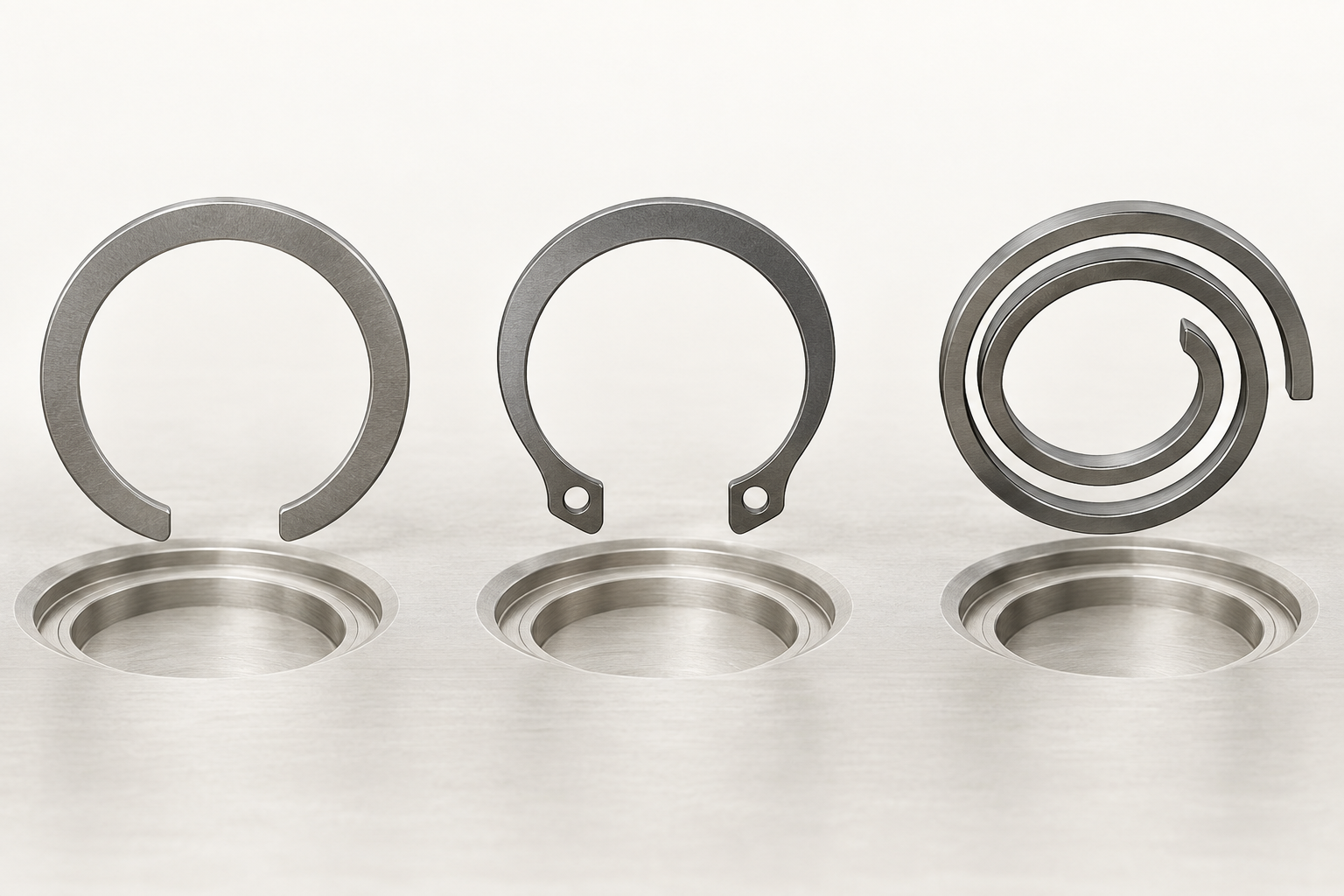
A constant-section ring may solve a radial-clearance problem without requiring spiral winding during installation. A tapered circlip may remain the simplest choice when the existing groove and plier access are already verified. A spiral ring may suit an assembly that benefits from a lug-free multi-turn construction. None of those statements establishes a winner without the application inputs.
Avoid selecting by catalog silhouette. Two rings can look similar in a web image yet use different groove diameters, widths, edge details or application methods. When replacing an existing ring, compare the proposed part drawing with the current ring, groove and retained-component interface line by line.
The groove is part of the retaining system. Confirm its diameter, width, bottom radius, side-wall condition and distance from the shaft or housing end. A large radius, burr or tapered wall can keep the ring from seating against the intended load-bearing surface. Insufficient edge material can make the groove weaker than the ring.
The retained component also matters. Its corner break or chamfer should not climb over the ring or concentrate contact on a small edge. Check axial clearance and tolerance stack. A flat retaining ring creates a stop, but it does not automatically remove end play. If the assembly needs controlled preload or take-up, that is a separate spring-function decision.
Evaluate ring and groove capacity separately. The lower capacity controls. Include the actual thrust direction, static and cyclic components, shock, vibration and the chosen safety factor. Uniform section alone does not prove suitability for impact or reversing load. Application validation may require an assembly test using production materials and tolerances.
At speed, a retaining ring is affected by centrifugal force, balance, groove seating and the behavior of its open ends. Use the selected manufacturer’s rotational guidance. Do not infer high-speed suitability from continuous contact or from a lug-free shape. Provide shaft or housing speed, orientation, vibration and any speed transients during selection.
Installation stress is another design input. An external ring can be permanently distorted if expanded too far; an internal ring can be damaged if contracted beyond its allowed limit. The tool should apply controlled, aligned movement and release the ring into the groove without twisting it. If assembly access is limited, confirm the installation path before committing to the ring family.
Material and finish should match temperature, corrosion, cleanliness and lubrication. A finish can change thickness and friction. Stainless or other material choices can change spring behavior and strength as well as corrosion response. Use only options approved for the exact ring series; do not transfer a material or finish from a visually similar ring.
Service requirements can be decisive. If the ring must be removed without damaging the shaft, housing or retained component, provide tool access and a defined removal feature. A ring that installs easily on the production line may be unsuitable where field access is poor or repeated disassembly is expected.
Stop before substitution when the existing drawing specifies a supplier series, when groove dimensions are unavailable, when load or speed is near a limit, or when the assembly is safety-relevant. Also stop if the proposed ring uses a different end form, material, thickness, free diameter or installation method. Nominal diameter is not proof of interchangeability.
A valid comparison needs both controlled part drawings. Review groove dimensions and tolerances, ring section, free state, installed envelope, thrust face, tool path, material, finish and capacity basis. If any of those inputs changes, document the engineering decision and determine whether first-article or functional testing is required.
Substitution also needs a failure-mode review. Ask what happens if the ring is not fully seated, if the groove edge deforms, if the retained component shifts, or if removal damages the assembly. Those questions determine which inspection and validation steps matter. They also prevent a purchasing change from being treated as a simple commercial equivalent when it alters installation or service risk.
For a new design, freeze the ring series only after the supplier’s controlled data and the assembly drawing agree. For an existing design, preserve the approved ring and groove relationship unless an engineering change formally validates the alternative.
Do not turn a marketing description into a drawing callout. “Constant section” identifies a family characteristic. The released specification should identify the exact standard or supplier series, size, material, finish and inspection requirement that purchasing and quality can verify.
TG Eugene’s product catalog provides the route for a retaining-ring inquiry, but no dedicated constant-section SKU or stock range has been verified for this article. Submit the assembly drawing and the inputs above so the appropriate product family can be confirmed before a quotation or substitution decision.