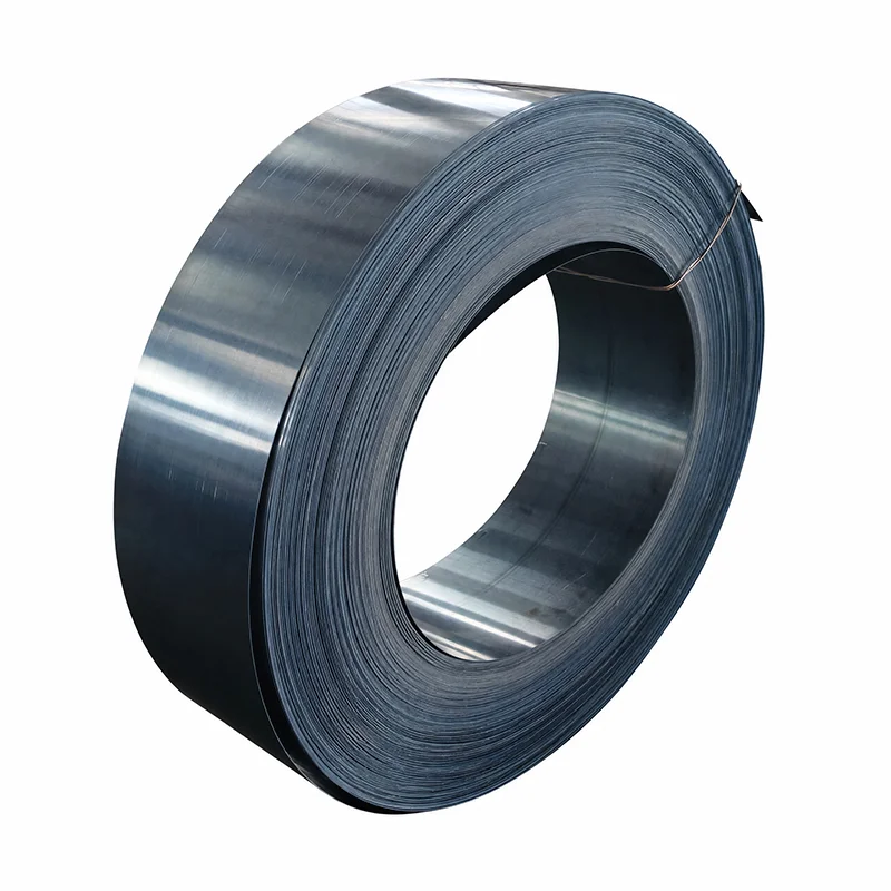
 Wenzhou Eugene Technology Co., Ltd.
 When a maintenance engineer in Suzhou pressed a new retaining ring into a gearbox bore, the ring appeared seated, then sprang out during a low-speed run. The team repeated the installation with greater force and saw the same rapid failure. A dimensional review showed the bore groove was correct; the root cause was a mismatched tool nose angle and an internal ring whose lug holes were not aligned with the pliers. The lesson was specification and process control, not a defective ring.
Summary: Successful snap-ring work depends on matching ring diameter, groove geometry, material condition, and tool access. DIN 472 internal rings are dimensioned for bores, while tool selection should follow the manufacturer’s hole size and angle guidance; a controlled installation check can prevent a single ejected ring from creating hours of rework. Confirm the drawing, use calibrated internal circlip pliers, verify full seating through 360 degrees, and document the check before release.
Internal circlip pliers control snap ring installation in a bore.
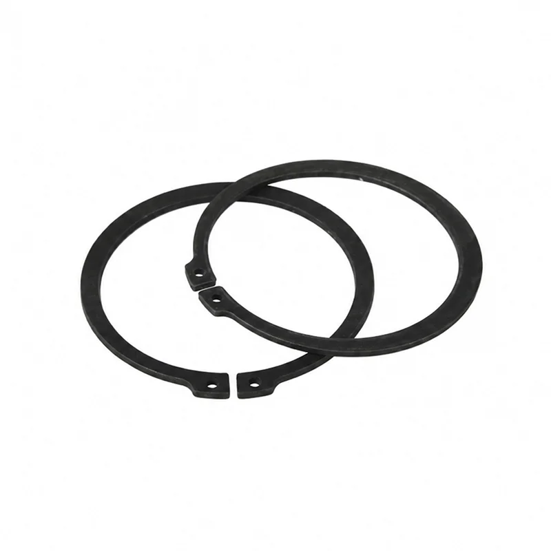
An internal circlip is an axially retaining ring fitted inside a machined bore. Its lugs provide holes for a spreading tool, and its body transfers thrust into the groove wall. Internal circlip pliers open the ring in a controlled arc so the operator can clear the bore, place the ring over the groove, and release it without twisting the section.
For production work, select a tool whose tip diameter fits the lug holes without bottoming. Excessive tip clearance allows the ring to cock; a tip that is too large damages the holes. The tool’s opening stop is equally important: spreading beyond the ring maker’s recommended maximum can yield the steel and permanently enlarge the ring. Smalley’s installation manual illustrates why controlled expansion and alignment matter even when the ring is not a Smalley design.
Operators should keep the ring square to the bore axis. A short, smooth squeeze on the internal circlip pliers is safer than a rapid snap. If the ring resists entry, stop and inspect the groove, burrs, and tool engagement rather than adding torque. This simple pause protects both the ring and the bore finish.
An internal circlip snap ring requires matched dimensions, material, and groove fit.
The internal circlip snap ring is a system with three interfaces: ring, groove, and retained component. Start with the nominal bore and groove drawing, then check free diameter, radial section, groove width, groove depth, and edge radius. A ring that fits the bore but not the groove can bottom on one flank, leaving a hidden axial gap.
DIN 472 provides dimensional conventions for retaining rings for bores; it is a product standard, not proof that every assembly will carry a specific load. Use the standard table as a baseline and compare the supplier drawing for tolerances, chamfer limits, and permissible thrust direction. For a practical size cross-check, review Eugene’s internal snap ring size chart alongside the controlled engineering drawing.
Material and finish determine corrosion behavior, spring recovery, and temperature capability. An internal circlip snap ring in carbon spring steel may suit dry indoor equipment, while stainless grades are often selected for humidity, washdown, or chemical exposure; the correct choice depends on the media and duty cycle. Ask for material designation, hardness range, and coating details rather than accepting a generic “stainless” statement.
Measure the groove with a calibrated depth micrometer or optical comparator where access is limited. Record at least three points around the circumference. A go/no-go ring gauge can verify bore size, but it cannot replace a groove inspection. If the application is safety-critical, conduct a proof-load or axial-retention test that represents the real load path.
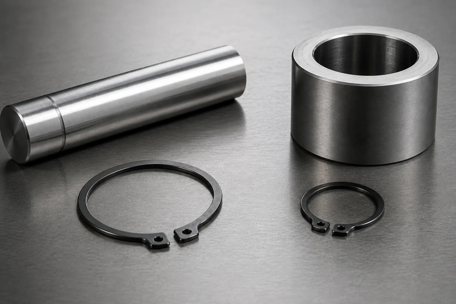
An internal circlip needs repeatable inspection and handling controls.
Before installation, deburr the groove, clean oil and chips, and confirm the internal circlip snap ring marking faces the specified direction when thrust is directional. Set the internal circlip pliers stop to the ring supplier’s maximum opening. Keep the tool tips fully engaged in both holes, expand only enough to pass the bore, and release gradually over the groove.
Use a three-point inspection: visual seating, tactile continuity, and dimensional confirmation. Visually trace both ring edges around the bore; a continuous shadow line indicates that the ring is not perched on a burr. Sweep a non-marring probe around the accessible edge to feel for a high spot, then measure axial clearance with a feeler gauge where the design allows it. Never strike the ring with a punch to “finish” seating.
For line qualification, perform a first-piece check and then sample at a frequency set by risk analysis. A simple control plan can record ring lot, operator, tool ID, groove gauge result, and final seating status. If a ring ejects, quarantine the lot and inspect the groove and tool together; replacing rings alone can hide a recurring process cause.
Tool maintenance is part of quality. Check tip wear, parallelism, return-spring action, and jaw stop drift at a defined interval. Lubricate only where the tool maker permits; oil on the lugs can reduce grip. A worn pair of internal circlip pliers may still “work” for an operator while creating inconsistent spread for the next shift.
Internal circlip pliers approaches affect efficiency, durability, and total cost.
Different tools can install the same ring, but they do not create the same risk profile. The table below is a decision aid; actual suitability depends on ring size, access, production volume, and operator training.
| Approach | Performance and efficiency | Compatibility and durability | Unit-cost tendency | Rework and TCO effect |
|---|---|---|---|---|
| Fixed-tip manual internal circlip pliers | Fast for a stable ring family; tactile feedback is strong | Best when lug-hole size and angle are consistent; tips wear over time | Low to medium | Low purchase cost, but wrong tip fit can increase ejections |
| Interchangeable-tip pliers | Setup takes longer, then supports several diameters | Broad compatibility; interfaces need cleaning and torque checks | Medium | Can reduce tool count and changeover waste when controlled |
| Pneumatic or powered spreader | High cycle consistency in repetitive lines | Requires guarded access, air quality, and preventive maintenance | Medium to high | Useful when labor dominates; downtime cost rises if service is weak |
| Improvised screwdriver or punch | Slow and difficult to control | Poor compatibility; can nick ring and groove | Apparently low | Highest hidden cost through damage, escapes, and injury exposure |
Illustrative cost logic: if a failed installation consumes 20 minutes of labor, a replacement seal, and a line restart, ten failures per month can outweigh the price difference between basic and interchangeable tools. Use your own loaded labor rate, scrap value, and downtime rate; label the result as an internal business case, not a universal saving.
Internal circlip specifications manage standards, load, and supplier risk.
Standards help align drawings and purchase orders, but they do not eliminate engineering judgment. DIN 472 addresses internal retaining-ring dimensions; ISO 9001 describes a quality-management framework rather than a ring geometry; ASTM E18 is a Rockwell hardness test method that can support incoming inspection but is not a circlip certification. State the exact edition and acceptance criteria in the purchase specification.
| Control point | Evidence to request | Why it matters commercially |
|---|---|---|
| Geometry | Controlled drawing, dimensional report, gauge records | Prevents bore/groove mismatch and line stoppage |
| Material and heat treatment | Mill certificate, grade, hardness method and range | Supports corrosion and spring-back decisions |
| Load validation | Test method, fixture, axial load and failure mode | Separates rated performance from marketing language |
| Traceability | Lot code, packing record, change notification | Enables targeted containment instead of broad recalls |
Load capacity depends on groove strength, ring section, thrust direction, and stress concentration. An internal circlip must be evaluated with its housing rather than as an isolated part. Smalley’s load-capacity guidance explains the variables; its selection guide is useful for framing a design review. NASA’s technical report on retaining-ring behavior (NASA-CR-186548) is a primary reference for engineers evaluating ring stresses and installation effects.
Unsupported compliance claims create commercial risk. A supplier should not imply that a DIN reference guarantees a complete assembly rating, nor that a test method equals certification. Tie every claim to the destination market, intended use, verified documentation, and the actual revision of the drawing.
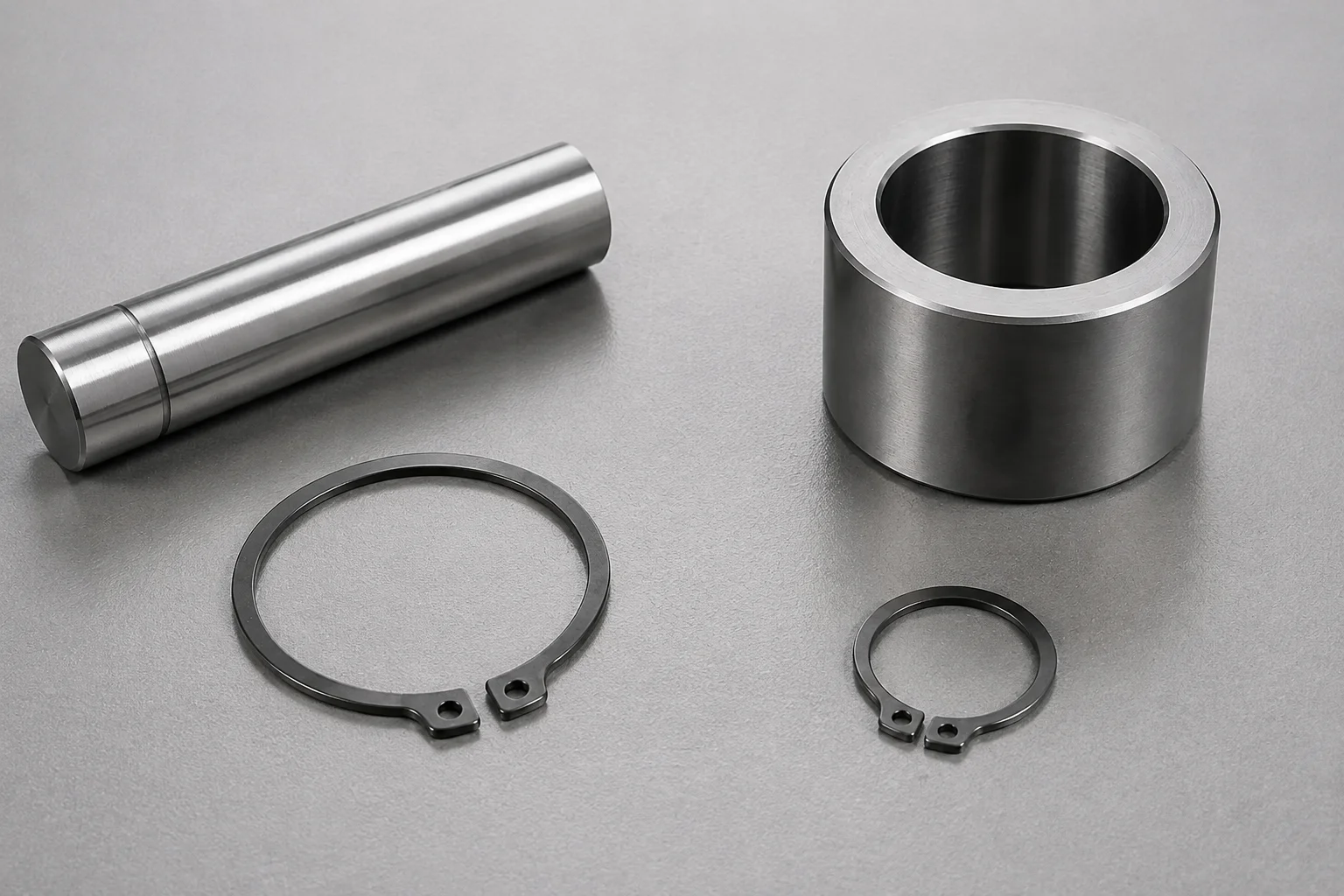
An internal circlip supplier should support a controlled OEM release process.
Procurement teams can reduce surprises by using a short release sequence:
- Send the bore, groove, load direction, environment, temperature, and target quantity with the RFQ for the internal circlip snap ring.
- Request a drawing, material/finish declaration, lot traceability, and sample measurement report.
- Run a first-article fit check with the production internal circlip pliers, the internal circlip snap ring, and the actual groove gauge.
- Approve a control plan covering tool checks, seating inspection, packaging, and change notification.
- Review field returns by failure mode; distinguish ring fracture, groove damage, tool misuse, and design overload.
Eugene (Wenzhou Eugene Technology Co., Ltd.) supports B2B buyers with configurable retaining-ring sourcing and documentation discussions. Buyers can review the circlips category and the DIN 472 product page, then align the selected part with their own drawing and validation plan. We recommend treating supplier responsiveness and evidence quality as part of total cost, not as a soft purchasing criterion.
How to remove internal circlips?
Use internal circlip pliers to expand the ring just enough to clear the groove, then lift it out without twisting. Protect the bore with a controlled grip and eye protection because stored spring energy can eject the ring. If the lugs are damaged, stop and use a replacement ring rather than forcing a screwdriver into the groove.
Are internal circlips reusable?
Reuse is acceptable only when the drawing or supplier guidance permits it and inspection shows no permanent spread, nicks, corrosion, or loss of spring-back. Measure an internal circlip snap ring against the approved limits and consider the duty cycle. For safety-critical or high-cycle assemblies, a new ring is usually the lower-risk choice.
What are internal circlips used for?
They retain bearings, gears, seals, pistons, and other components inside a bore while allowing compact axial positioning. The groove carries the thrust into the housing, so the housing material and edge geometry are as important as the ring. A internal circlip should not be substituted without confirming the load path and groove.
What is an internal metric circlip?
An internal metric circlip is dimensioned for a metric nominal bore and matching groove, commonly specified with millimetre values and standards such as DIN 472. “Metric” describes the dimensional system, not a guaranteed material or load rating. Verify the supplier drawing and grade for the destination application.
What are metric internal circlip sizes & dimensions?
Sizes are identified by nominal bore and include free diameter, radial section, groove width, groove depth, and lug geometry. Use a controlled chart for initial selection, then confirm tolerances on the part drawing; a supplier size reference can support that first pass. Do not infer load capacity from bore size alone.
How do circlips work?
An internal circlip snap ring seats in a groove and converts axial force into radial contact with the groove wall. Internal rings contract against a bore groove after the tool is released, while external rings expand into a shaft groove. Correct groove strength, seating, and orientation determine whether the mechanism works reliably.
References
- Smalley Spirolox retaining rings overview.
- Smalley retaining-ring installation manual.
- Smalley retaining-ring selection guide.
- Smalley ring design and load capacity.
- NASA technical report on retaining-ring performance.
The reliable principle is simple: match the ring, groove, and tool as one engineered system, then verify seating before the assembly leaves the station.
For a drawing review, sample request, or application-specific retaining-ring recommendation, contact Eugene’s engineering team with your bore, groove, load, environment, and annual volume.