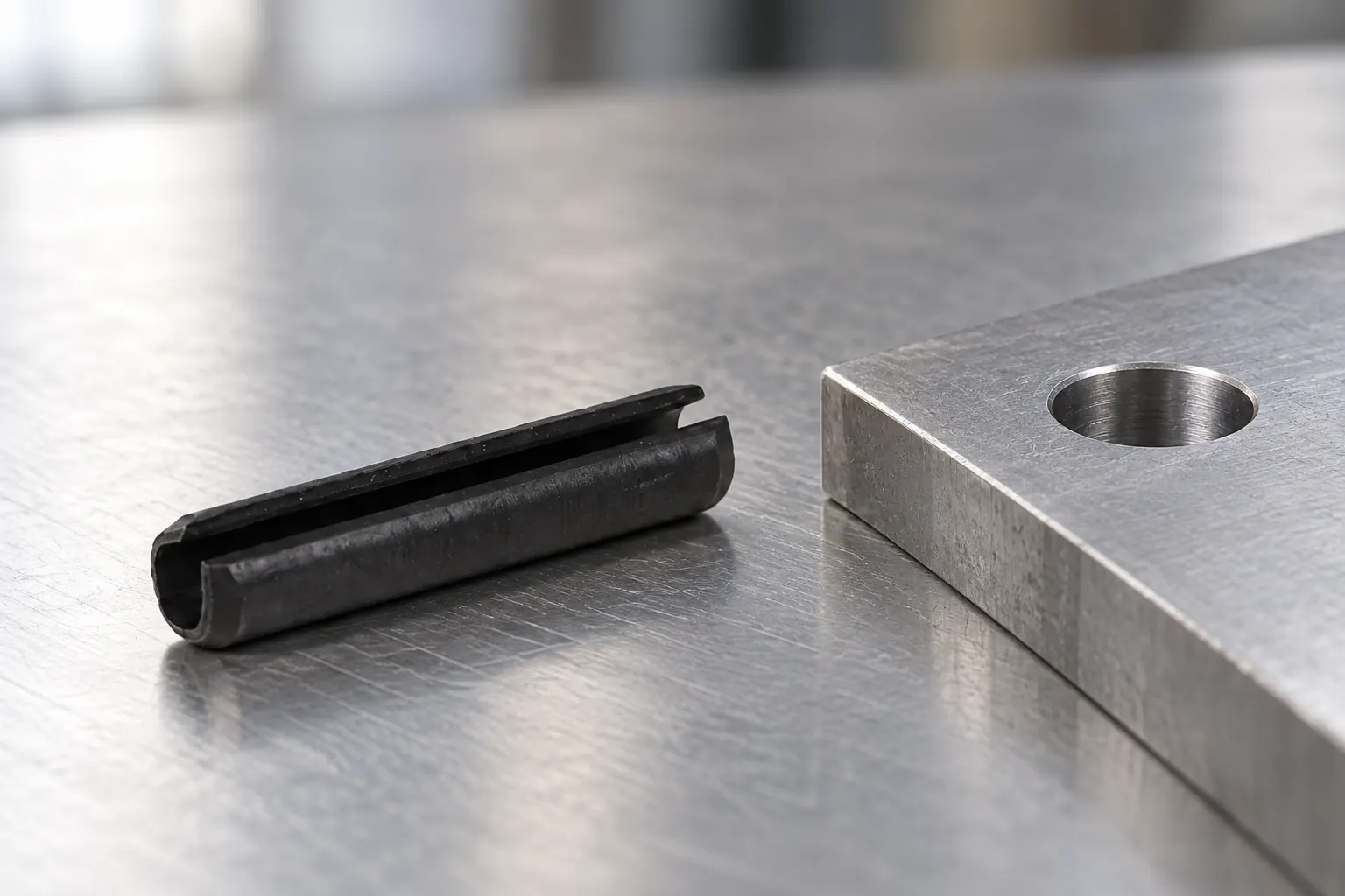
ISO 8752 slotted spring pins are hollow, longitudinally slotted pins that compress during installation and press against the receiving hole. The pin’s nominal diameter is only one part of the specification. A reliable selection also controls the standard reference, length, free diameter, chamfer, material, finish, hole range, and host-part condition.
These fasteners are also called metric roll pins, tension pins, or slotted spring pins. Those names describe the product family, but they do not define one interchangeable size. The drawing and purchase order should state the exact pin type and the conditions that affect fit.
A slotted spring pin has a longitudinal slot along a rolled cylindrical wall. When the pin enters a hole, the wall compresses. Its spring action then produces continuous radial pressure against the hole wall.
This mechanism lets the pin accommodate some variation in the mating hole. It does not remove the need to control the hole. Hole diameter, roundness, alignment, surface condition, host material, entry chamfer, and assembly force can change the result.
The slot also explains why a slotted spring pin is not the same as a solid dowel pin. A solid pin depends on a defined interference or transition fit. A slotted pin uses elastic compression in its wall. The two parts may serve related locating or retaining tasks, but their hole specifications and installation behavior are different.
Heavy-duty and light-duty slotted spring pins should also remain separate in the inquiry. A heavy-duty design normally has a thicker wall and a different dimensional reference from a light-duty pin. Do not select a replacement because both products are listed as roll pins.
ISO 8752 is the common metric reference used for heavy-duty slotted spring pins. DIN 1481 appears frequently in older drawings, catalogues, and supplier searches. A buyer may therefore encounter both names for the same general fastener family.
That does not mean the two references should be treated as identical without checking the governing document. The standard-oriented reference used for this guide describes DIN 1481 as the older basis and notes differences in some chamfer options. A legacy drawing should retain its original requirement until engineering approves an updated standard.
When a project specifies ISO 8752, write the complete designation rather than adding “DIN 1481 equivalent” as an uncontrolled shortcut. Include the nominal diameter, length, material, finish, and any required inspection document. If the project allows DIN 1481 parts, define whether the substitution applies to the full part or only to selected dimensions.
The same discipline applies to the phrase “metric roll pins.” It is useful as a search term, but it does not identify the heavy-duty type, standard, material, or finish. Use it in product discovery, then convert it into a controlled drawing or purchase description.
Start with the nominal diameter shown in the selected ISO 8752 reference. Then check the pin’s free outside diameter and the recommended receiving-hole range. These values answer different questions: the nominal size identifies the pin designation, while the free diameter describes the uninstalled part before compression.
The table below is a limited reference extracted from a manufacturer technical guide. It shows common metric sizes and the guide’s recommended hole ranges. Treat it as a starting point for design review, not as permission to replace the governing standard or the application’s drawing.
| Nominal pin diameter | Recommended hole minimum | Recommended hole maximum | Selection note |
|---|---|---|---|
| 2 mm | 2.00 mm | 2.10 mm | Confirm hole quality and entry condition. |
| 3 mm | 3.00 mm | 3.10 mm | Confirm alignment through all joined parts. |
| 4 mm | 4.00 mm | 4.12 mm | Check the host material before setting insertion force. |
| 5 mm | 5.00 mm | 5.12 mm | Keep the hole range tied to the selected pin type. |
| 6 mm | 6.00 mm | 6.12 mm | Verify the pin will not bottom before full engagement. |
| 8 mm | 8.00 mm | 8.15 mm | Check access, chamfer and insertion tooling. |
| 10 mm | 10.00 mm | 10.15 mm | Review load direction and joint geometry. |
| 12 mm | 12.00 mm | 12.18 mm | Confirm the selected standard and material condition. |
Do not read the table as a universal formula. A hole at the upper limit may behave differently from a hole at the lower limit. The host material, burrs, coating, hole depth, temperature, insertion speed, and joint load can all affect assembly.
For that reason, do not size the hole from the visible outside diameter of a loose pin alone. The pin may be measured at more than one location, and the slot region can affect how a measurement is taken. The technical guide specifies its own measurement method and inspection conditions. Follow the selected standard and supplier drawing when the values differ.
A complete slotted spring pin specification separates the following fields:
Finish selection is part of the application, not only an appearance choice. A coating can affect dimensions, friction, corrosion behavior, and the order in which inspection takes place. State whether dimensional values apply before or after plating when the selected standard or supplier specification requires that distinction.
TG Eugene lists an ISO 8752 slotted spring pin route using 65Mn and a black-oxide finish. This is first-party product information. It should guide the product conversation, but it does not replace an approved drawing, certificate, or order-specific inspection record.
The receiving hole should be defined with the pin, not in isolation. State the hole diameter or tolerance, the hole-making process, the number of joined components, the required alignment, the available depth, and the entry condition.
For a through joint, check whether the slot can pass through the complete stack without interference. For a blind hole, define the usable depth and the clearance below the installed end. If the pin must locate two parts, control the relationship between the holes rather than relying on the pin to correct a misaligned assembly.
Host material also matters. A hole in soft aluminium, a hardened steel plate, and a sintered component can react differently to the same pin. Test the selected pin and hole process together when insertion force, joint damage, retention, vibration, or repeated assembly matters.
Use the checklist to compare quotations on the same basis. If a supplier proposes a DIN 1481 or another roll-pin substitute, ask for the exact dimensional and material cross-reference before accepting it. The final decision belongs to the drawing owner because the hole, joint and load determine whether the substitution is suitable.
They refer to the same general heavy-duty metric slotted spring-pin family, and older documents may use DIN 1481. Treat the relationship as a standards and edition question, not as an automatic approval for every size and feature. Keep the drawing’s original reference or obtain engineering approval for the specific substitution.
Specify the hole with the selected pin standard, nominal diameter, depth, tolerance or range, entry condition, alignment and host material. Use a manufacturer or standard table as a reference, then confirm the actual hole process and assembly result for the application.