An e clip removal tool should release the clip in a controlled direction while keeping the ring and shaft supported. Maximum force is not the goal. Controlled movement prevents the E-clip from launching, twisting, or scoring the shaft during removal.
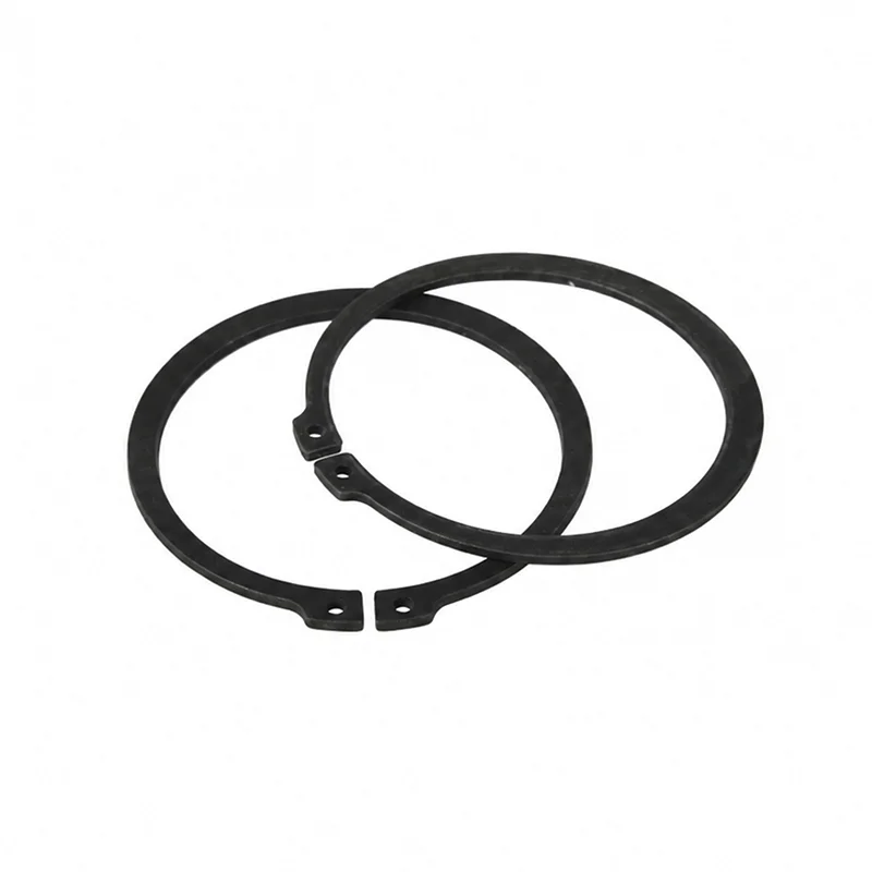
An E-clip is a radial-entry retaining ring that sits in a groove on an external shaft. Its open shape gives a tool access to the clip, but that access also creates a release path. The correct method depends on the clip size, groove condition, surrounding clearance, and whether the assembly can safely contain the ring.
Stop the assembly and support the retained component before touching the ring. Remove grease, loose debris, and any cover that blocks a clear view of the clip. A clean work area makes it easier to see whether the clip is seated in the groove or already damaged.
Do not begin by prying against a nearby bearing, gear, or thin housing edge. That can transfer force into the assembly instead of the clip and can damage the part you intend to keep.
Choose a tool that reaches the opening and applies force to a stable part of the clip. For accessible assemblies, use the ring manufacturer’s or approved service procedure and its specified applicator; use a slim flat tool only when that procedure explicitly permits it and the clip is fully contained. A purpose-designed E-clip tool gives better control when the clip is recessed or the assembly must remain protected.
Tool access matters more than the tool name. Check the jaw or tip width, approach angle, clearance around the shaft, and the direction in which the ring will move. Do not select a tool only because it fits the clip opening. It must also allow the operator to contain the ring and avoid the shaft surface.
Instructions about how to remove E clips should begin with the assembly, not a preferred tool model. A removal method using an E-clip tool that works on an open bench may be unsafe in a recessed housing. Confirm the access angle and release path before applying force.
Never force a clip that is only moving on one side. Uneven movement can bend the ring or mark the groove. Reset the tool, improve support, and inspect the exposed edge before trying again.
Removal is not complete when the clip is off the shaft. Inspect the clip for cracks, permanent spreading, twisted legs, sharp damage, or marks caused by the tool. Check the shaft groove for burrs, raised material, corrosion, and damage that could prevent the replacement ring from seating.
Also inspect the retained component. A ring that was difficult to remove may indicate a damaged groove, contamination, or an assembly condition that needs correction. Clean parts before measuring or reinstalling them, and compare the result with the approved drawing when one is available.
| Inspection point | What to check | Decision |
|---|---|---|
| Clip body | Cracks, distortion, tool marks, or loss of shape | Replace if the ring no longer returns to its specified form. |
| Open legs | Uneven spreading or damaged edges | Do not rely on a deformed engagement area. |
| Shaft groove | Burrs, corrosion, debris, and edge damage | Correct the groove condition before fitting another ring. |
| Retained part | Axial play, scoring, or damage near the shoulder | Check the assembly cause before reinstallation. |
Replace the E-clip when inspection finds a crack, permanent deformation, damaged engagement legs, corrosion, or a profile that no longer seats securely. Replacement is also appropriate when the assembly drawing or maintenance procedure specifies a new ring after removal.
Do not assume every removed E-clip has the same reuse rule. Reuse depends on the ring design, material, service condition, removal method, and the approved assembly requirement. When the clip was forced off or the tool slipped, replacement is safer than treating the old ring as unchanged.
For a DIN 6799 E-type retaining ring, the product page is a useful way to confirm the component family before selecting a removal approach. It does not replace the drawing, groove inspection, or the assembly’s service instruction.
Use a guard, cloth, or small enclosure around the clip while keeping the tool visible and aligned. The barrier should block the release path without forcing the tool into the shaft or preventing a clear inspection.
Replace it when it is cracked, permanently spread, corroded, tool-damaged, or no longer seats correctly. Follow the assembly drawing or maintenance instruction when it requires replacement after removal.