 Wenzhou Eugene Technology Co., Ltd.
 Summary: An external retaining ring for shaft duty is a compact axial-stop component, but it works only as a system of shaft diameter, groove geometry, retained-part chamfer and installation method. Start from the nominal shaft size, then verify groove diameter and width against the applicable ring table; ISO 286-1 provides the language for agreed linear-size tolerances, while a DIN geometry reference does not by itself prove suitability for every load, speed or safety-critical use. Measure the groove after machining, specify the retained component’s contact face, and confirm full seating before releasing production.
How should external retaining ring dimensions be checked before a shaft groove is released?
Used well, this groove-seated ring gives designers a low-profile way to restrain bearings, gears, pulleys, collars and similar components on a shaft. Used casually, it can introduce axial play, edge loading, assembly damage and avoidable inspection cost. The practical question is not whether a catalogue ring fits over a nominal diameter; it is whether the complete joint has enough geometry, material condition and process control for the duty cycle.
The nominal shaft diameter is the starting point, not the final selection criterion. Published external retaining ring dimensions normally relate a nominal shaft range to ring thickness, radial section, groove diameter, groove width and allowable edge form. Read the relevant product drawing as one set: a correct nominal size can still fail if the groove is too wide, too shallow or formed with a radius that prevents the ring from reaching its seat.
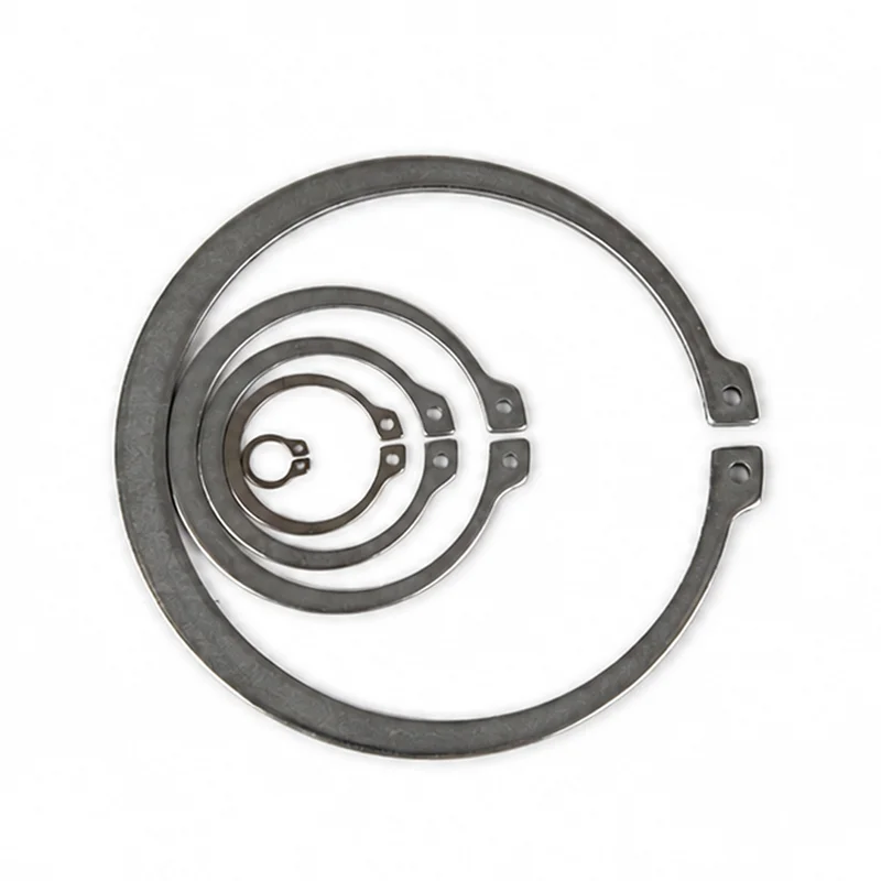
Measure the functional features, not just the visible groove
For each shaft family, record nominal diameter, actual shaft diameter, groove bottom diameter, groove width, edge radius or chamfer, ring free diameter and the retained part’s bore chamfer. ISO 286-1 is useful here because it establishes a common system for tolerances and fits on linear sizes; it does not supply a universal groove design. A 0.02 mm variation can be meaningful on a small groove, so the drawing should state the inspection method and datum rather than leaving operators to infer intent.
| Feature | What to confirm | Why it matters | Typical control |
|---|---|---|---|
| Nominal shaft size | Applicable ring series and diameter range | Establishes the catalogue family | Micrometer or calibrated calliper |
| Groove bottom diameter | Specified diameter and tolerance | Controls radial engagement | Go/no-go gauge or micrometer method |
| Groove width | Width, parallelism and burr condition | Influences side clearance and rocking | Gauge pins or optical measurement |
| Groove edges | Radius, chamfer and surface damage | Prevents incomplete seating and stress concentration | Profile check and visual inspection |
| Retained component | Bore lead-in and contact shoulder | Determines usable axial face contact | Assembly drawing review |
Do not substitute a material-thickness measurement for a groove inspection. Nominal ring thickness is only one contributor to axial clearance; plating, burrs, component chamfers and groove-width variation can change the assembled result. Where a printed DIN series is used, cite the exact revision and supplier drawing in the purchase specification, since standards define geometry and interchangeability rather than blanket fitness for a particular machine.
Which installation controls keep an external retaining ring for shaft assemblies seated?
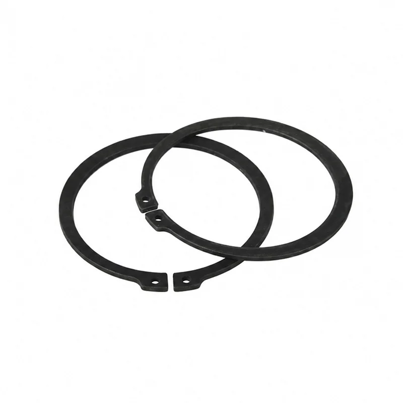
Installation is a controlled elastic expansion, not a test of how far a ring can be spread. Use pliers designed for the ring holes, expand only enough to clear the shaft, keep the tool square to the shaft axis, and release without dragging the ring across the groove edge. Over-expansion may leave permanent set or reduce contact with the groove; forcing with screwdrivers can nick the ring, shaft or coating.
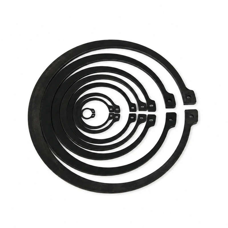
Build a short, repeatable acceptance check
A useful work instruction has three steps: verify part identity before fitting, visually confirm full circumference seating after release, then check that the retained component has the intended axial movement or preload. On repetitive machinery, add a fixture or camera check if a missed seat would be difficult to see. For plated or corrosion-exposed parts, agree whether salt-spray evaluation is required; ISO 9227 describes neutral salt spray and related methods, but it is a corrosion-test method rather than a general product certificate or a direct prediction of field life.
Assembly economics matter. A ring that costs little but requires rework after every damaged groove can cost more than a properly specified alternative. An illustrative calculation: if a 3-minute inspection prevents one 40-minute rework event in every 20 assemblies, the expected labour avoided is 2 minutes per assembly before considering downtime or scrap. The right input values depend on the plant; the point is to compare joint-level total cost, not piece price alone.
How do material, load direction and environment affect an external retaining ring?
The external retaining ring primarily resists axial movement by transferring load through the retained component, ring face and groove wall. It is not a substitute for a thrust bearing, a positive shoulder or a safety device when the load case requires those features. Consider peak axial load, reversing load, vibration, rotation speed, impact, temperature, lubricant, corrosion exposure and the consequence of release before choosing a series or material.
| Approach | Space use | Serviceability | Load-path clarity | Unit-cost tendency | TCO consideration |
|---|---|---|---|---|---|
| Retaining ring in groove | Compact axial envelope | Fast when access is available | Depends on groove and contact geometry | Usually low | Machining and inspection discipline are decisive |
| Machined shaft shoulder | Consumes axial length | No removable part | Direct bearing face support | Machining-dependent | Can reduce assembly steps but limits repositioning |
| Threaded nut and washer | Needs thread and access | Adjustable and removable | Clear when torque is controlled | Moderate | Locking method and service torque add work |
| Clamp collar | Adds radial and axial bulk | Simple to reposition | Friction-dependent unless shouldered | Moderate | May suit prototypes or frequent adjustment |
Material selection should follow the exposure and mechanical requirement. Carbon spring steel may be appropriate for protected indoor equipment; stainless options can be considered where corrosion resistance is necessary, with the actual alloy, hardness, finish and compatibility documented. Avoid a casual “stainless equals corrosion-proof” assumption: chlorides, crevices, temperature and mating materials all influence risk. Buyers supplying machinery into the EU should also evaluate the intended product and documentation against the EU Machinery Regulation where applicable; a component’s DIN designation does not by itself establish machine-level compliance.
When should buyers specify an external retaining ring with the supplier?
Specify the interface whenever a drawing is new, a supplier is changed, a shaft material or coating changes, or field failures show axial displacement. A purchase order that names only the nominal diameter invites inconsistent interpretation. Instead, identify the standard or drawing, nominal size, material and finish, revision status, package/traceability need, required documents, incoming inspection plan and any functional validation. If the ring supports a safety-relevant or unusually high-load function, have the design authority define the load case and verification test.
For receiving inspection, distinguish a drawing requirement from a measurement decision. ISO 14253-1 addresses rules for proving conformance or nonconformance when measurement uncertainty is considered; it is especially relevant when a groove result falls close to a tolerance limit. Agree in advance on the measuring equipment, resolution, temperature condition and decision rule. That prevents a buyer, machinist and incoming inspector from reaching different conclusions from the same borderline part.
A practical selection sequence
- Classify the retained component and all axial load directions, including shock and reversing events.
- Choose a ring family that matches the shaft and available groove geometry, then check the supplier’s dimension table against the controlled drawing.
- Set tolerances, edge condition, surface finish and component chamfer as a single interface requirement.
- Define installation tooling and a seating check for the production or service environment.
- Review corrosion, documentation and destination-market obligations before approving a material or marketing claim.
For a design review, Eugene offers standard DIN-series circlips alongside custom fastening solutions; the useful conversation begins with the shaft drawing, duty conditions and inspection expectation. Engineers can compare the category options for an external retaining ring, examine the relevant DIN 471 external circlip product page, or use this guide on choosing retaining rings for shafts and bores before finalising a bill of materials.
What should a team verify before approving an external retaining ring for production?
Approval should join design, sourcing and quality rather than treating the ring as a commodity line item. For every external retaining ring for shaft application, verify drawing revision, dimension records, material/finish declaration where needed, sampling basis, installation trial and the retained component’s actual axial face. For machinery builders, linking this check to the wider machinery-manufacturing application review helps prevent a local fastener choice from conflicting with service access or assembly flow.
Keep the production record proportionate to risk. A non-critical service assembly may need a documented visual seat check and lot identification; a high-consequence location may call for first-article dimensions, a controlled assembly trial and traceable acceptance records. Review the choice after a design, material or process change. This approach gives procurement a clear comparison basis and gives quality teams evidence that the supplied part was evaluated as an interface, rather than accepted on nominal diameter alone.
Frequently asked questions
What is the difference between an external ring and an internal ring?
An external ring sits in a groove on the outside of a shaft, whereas an internal ring seats in a groove inside a bore. The load path and installation tools differ, so select from the component being retained rather than from a name alone.
How much axial load can an external retaining ring carry?
There is no responsible universal load value. Capacity depends on nominal size, ring section, groove geometry, shaft material, retained-part contact, dynamic conditions and the selected standard or supplier data; validate the specific assembly when the result has a high consequence.
Can I use a DIN 471 ring on any shaft with the same nominal diameter?
No. The shaft groove, tolerances, edge form and retained-part geometry must correspond to the relevant specification. DIN-style dimensional interchangeability is valuable, but it does not replace an application review.
Should I reuse a ring after removal?
Reuse should be allowed only when the applicable drawing, condition inspection and process rules permit it. Replace any ring showing distortion, damaged lug holes, coating damage, corrosion or uncertain seating history.
What inspection is most important after fitting?
Confirm complete seating around the groove and then verify the retained part bears on the intended ring face. If visual access is poor, use a defined gauge, fixture or documented functional check rather than relying on operator feel.
References
- ISO 286-1: ISO system for tolerances and fits
- ISO 14253-1: Inspection by measurement of workpieces and measuring equipment
- ISO 9227: Corrosion tests in artificial atmospheres — salt spray tests
- Regulation (EU) 2023/1230 on machinery
A retaining joint is only as dependable as the drawing, groove and installation discipline that support it. When your team is ready to turn those checks into a consistent supply specification, explore Eugene circlips and discuss the shaft interface.