A Belleville washer stack changes load and travel through disc orientation. Opposed discs in series increase available travel, nested discs in parallel increase force, and a series-parallel arrangement increases both. These are ideal relationships for identical disc springs. A real stack still needs checks for friction, guidance, tolerances, lubrication, and operating conditions.
| Arrangement | Disc orientation | Main change | Ideal reference |
|---|---|---|---|
| Series | Alternating, opposed cones | More axial travel | Force follows one disc; travel adds |
| Parallel | Nested in the same direction | More force | Force adds; travel follows one disc |
| Series-parallel | Nested groups arranged in opposition | More force and travel | Group force and group travel both scale |
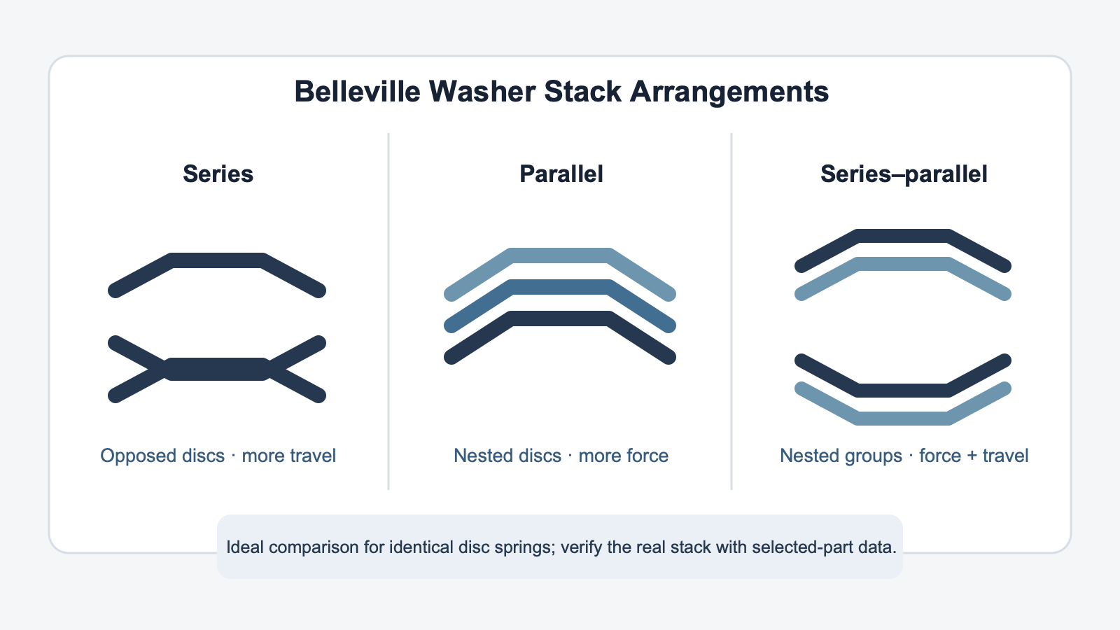
In a series stack, adjacent disc springs face in opposite directions. Each disc can deflect as the column shortens, so the individual deflections add. If an ideal stack contains s identical discs in series, its available travel is approximately s times the travel of one disc at the corresponding operating point.
The force does not multiply in the same way. Each disc carries the stack load, so the ideal force-deflection relationship remains close to that of one disc while total movement increases. This arrangement suits a design that needs more axial movement but can use the force range of the selected single spring.
Do not release a long series column from that rule alone. Contact friction and small dimensional differences can cause unequal movement through the stack. The guide diameter, outside clearance, compressed height, and end support also affect how the column behaves. Check these items before fixing the number of discs.
Evaluate more than the end points. The stack must deliver the required force at every specified working position, not only at free height or maximum compression. Record the minimum and maximum installed positions on the drawing so the calculation uses the same movement range that the assembly will see.
Parallel stacking places identical disc springs inside one another with their cones facing the same direction. The nested discs move through approximately the same travel. Their forces add, so an ideal group of p identical discs produces approximately p times the force of one disc at the same deflection.
This compact arrangement is useful when the assembly needs more force without adding the full height of separate opposed springs. It also creates sliding interfaces between the nested discs. Those interfaces introduce friction and can produce a difference between loading and unloading behavior. A catalog force multiplied by the disc count is therefore a starting relationship, not a finished stack curve.
Surface condition and lubrication deserve explicit treatment in the specification. If the application cycles, the review should also cover heat, wear, and the required life. These checks become more important as the number of contacting interfaces grows.
Assembly control also matters. Nested discs can appear correct from above while the count or orientation is wrong inside the group. A section view, group notation, and inspection point make the intended arrangement easier to verify before installation under the same released drawing.
A combined disc spring stack uses parallel groups placed in series. A simple way to describe the layout is p × s:
Ideal comparison: a p × s arrangement scales force by approximately p and travel by approximately s, relative to one identical disc at the corresponding per-disc condition.
For example, the notation 2 × 3 describes three opposed groups with two nested discs in each group. It identifies the arrangement clearly, but it does not establish an exact working load. The selected disc’s load-deflection data and the real stack conditions still control the calculation.
Start with the two outputs the assembly must provide: force over the working range and usable axial travel. Then compare those outputs with the installed envelope. This order prevents the stack from being chosen only because a drawing has room for a certain number of washers.
| Design need | First arrangement to evaluate | Main review point |
|---|---|---|
| More movement at a similar force level | Series | Stack length, guidance, and unequal deflection |
| More force within limited axial travel | Parallel | Interface friction, lubrication, and hysteresis |
| More force and more movement | Series-parallel | Group orientation, total height, and full stack curve |
If none of these routes fits the envelope, reconsider the single disc before adding more parts. A different disc geometry may reduce the required stack count and the number of friction interfaces.
Compare the free and installed stack heights at this stage. The assembly needs enough clearance for the intended movement, but it also needs a defined stop or permitted compression limit. Leaving either value undefined can turn an acceptable arrangement concept into an uncontrolled installed condition.
A complete request should identify the individual spring before it defines the stack. Include the applicable drawing or part reference and the current single-disc load-deflection data. Then state the required stack arrangement in words and with the p × s notation.
Add an assembly note that controls disc count and orientation. Where a guide is used, identify the guide surface and its relevant clearance rather than relying on a generic “guided stack” note. Inspection can then confirm the arrangement, free height, installed height, and selected product reference against the same released document.
TG Eugene’s DIN 2093 Belleville disc spring product family is a relevant starting point for product review. The product page identifies the family; the drawing and application data still need to establish the actual stack.
Do not multiply a catalog value without matching the operating point. The ideal relationships compare identical discs at corresponding deflection conditions. They do not convert one catalog number into a verified assembly result.
Do not omit orientation from the drawing. A count such as “six Belleville washers” does not tell production whether the discs are nested, opposed, or grouped. Add the orientation, p × s description, free height, and installed condition.
Do not treat the stack as frictionless. Parallel interfaces, guides, surface condition, and lubrication affect real loading and unloading. Use the ideal series and parallel rules to select a direction, then verify the finished arrangement with the selected disc data and application conditions.