To remove circlip snap ring parts without damaging the groove, match the tool to the ring geometry, control the release path, and inspect the shaft before fitting another ring. The safest method uses steady, limited force rather than prying harder.
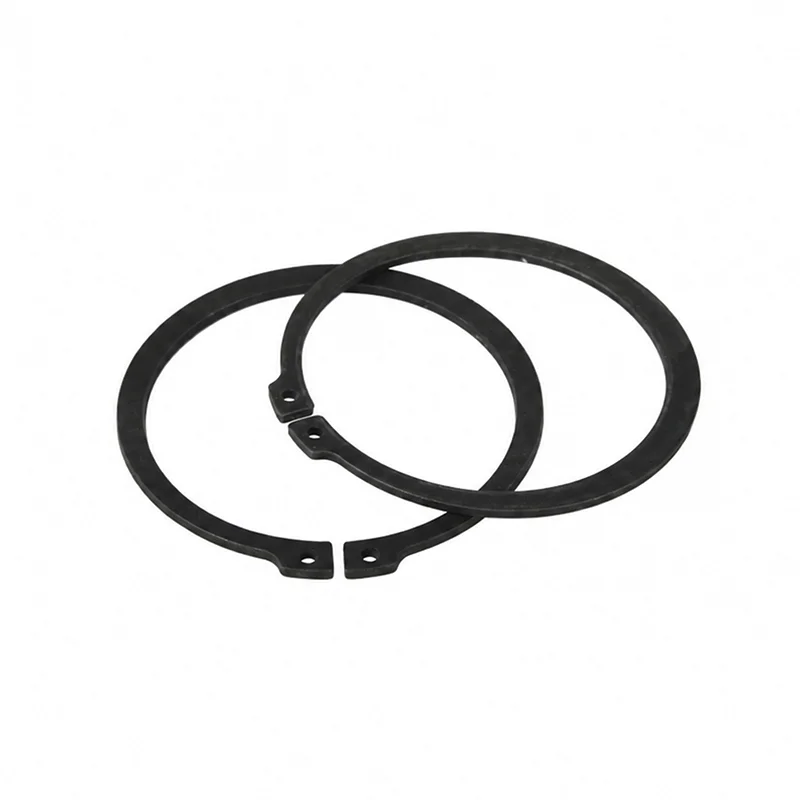
A circlip, also called a snap ring or retaining ring, holds a component against axial movement. Some rings fit an external shaft groove; others sit inside a bore. That distinction controls the tool direction and the way the ring should be contained during removal.
Before removal, follow the equipment maintenance procedure and make the ring and groove visible. Confirm whether the ring is external or internal. Look for holes, lugs, an opening, or another feature intended for tool access. Do not assume that a familiar name identifies one universal part.
The phrase snap ring removal covers several ring designs, so select the tool from the actual part geometry rather than from the search term alone.
Use circlip pliers or another approved removal tool that reaches the ring without bearing on the shaft, housing, or groove edge. External-ring pliers normally open the ring; internal-ring pliers normally compress it. Match the tip shape and working range to the ring and available access.
Check the approach angle, clearance, and expected movement before applying force. If the ring does not move with controlled force, stop and follow the maintenance procedure rather than improvising against a precision surface.
Keep the tool aligned with the ring throughout the movement. If the ring resists, reset the tool, improve access, and investigate the cause before continuing.
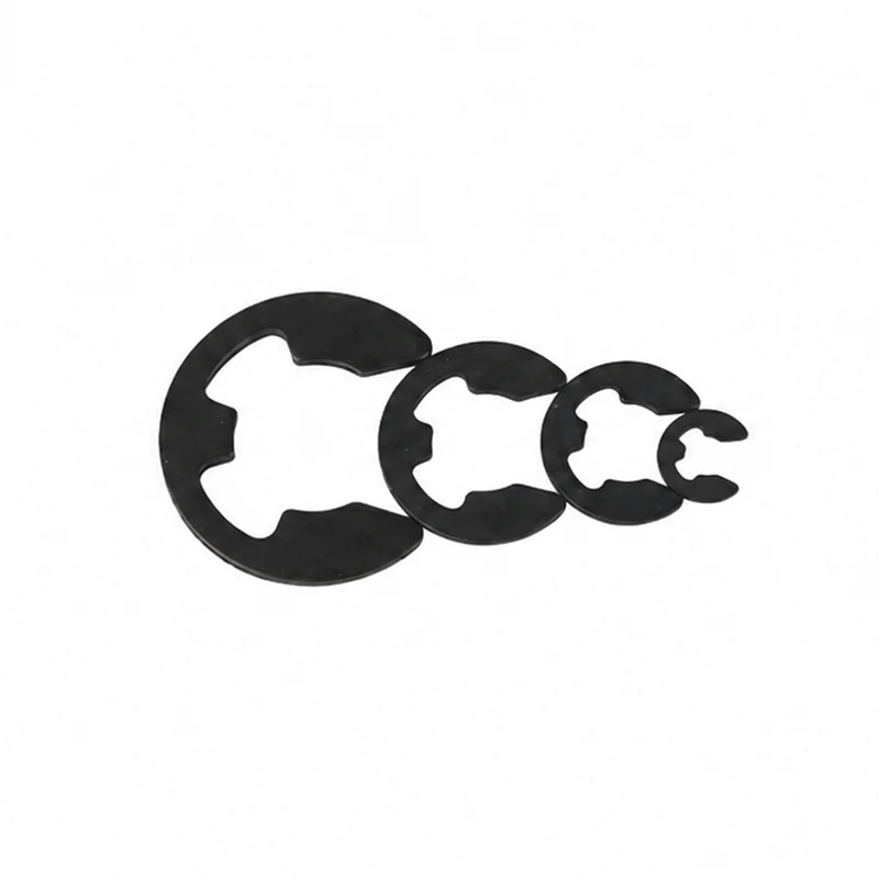
Removal is only complete after inspection. Check the circlip and groove against the approved drawing or maintenance instruction. The ring must meet the assembly’s documented acceptance requirements before reuse.
Record the ring position and the condition you found before reassembly. If the part belongs to a production line, keep the drawing revision and inspection result with the job record. That record separates a controlled replacement from a guess based on a ring that happens to look similar.
| Inspection point | Check | Action |
|---|---|---|
| Ring | Condition against the approved drawing | Follow the documented acceptance decision. |
| Groove | Condition and seating surface | Correct any documented nonconformity before reassembly. |
| Assembly | Retained component and axial movement | Follow the assembly maintenance instruction. |
Reuse depends on the ring design, service condition, removal method, and the approved assembly instruction. Use the drawing or maintenance procedure to decide whether the removed ring meets the assembly’s acceptance requirements. If that document requires a new ring after removal, follow that requirement.
Use pliers designed for internal rings in bore grooves and pliers designed for external rings on shafts. Confirm the tip shape, working range, and available clearance against the ring and the approved drawing before removal.
Use the ring design, service condition, removal method, drawing, and maintenance instruction to make the decision. Replace it when the approved inspection finds damage or when the procedure requires a new ring.
For a first-party component reference, review TG Eugene’s DIN 471 external circlip. For general retaining-ring removal and tool guidance, consult Rotor Clip’s installation and removal guide. Use both as context, together with the approved drawing and maintenance instruction for the specific assembly.