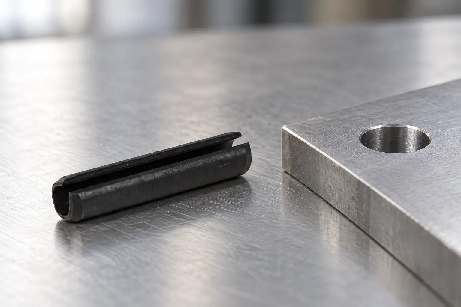
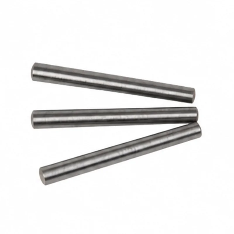
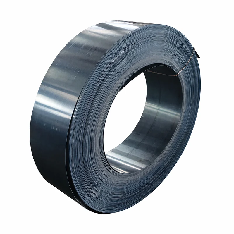
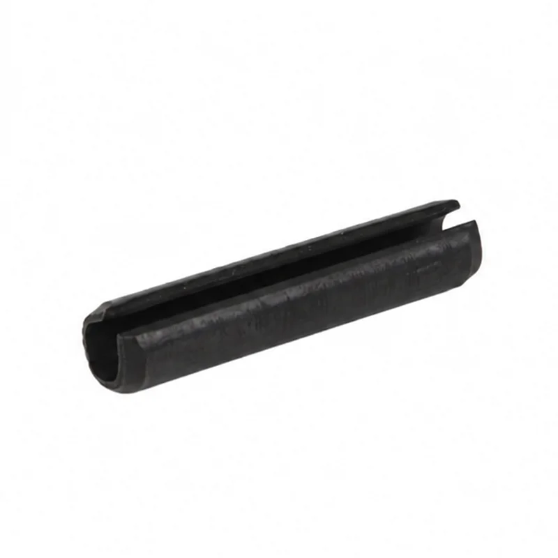
What is a roll pin? The term commonly means a spring pin: a hollow metal pin that compresses as it enters a prepared hole and then presses outward against the hole wall. That spring action helps the pin remain in place and accommodate limited variation in the assembly.
“Roll pin” does not identify one universal construction. The two basic families are slotted spring pins and coiled spring pins. Their cross-sections, installation behavior, and load response differ, so a drawing should name the type and governing standard rather than use the nickname alone.
A spring pin has a free outside diameter larger than the recommended receiving hole for its approved application. Installation compresses the pin. The pin then exerts radial force against the hole wall.
This behavior separates a spring pin from a solid dowel. A solid dowel relies on the dimensional relationship between a rigid pin and the mating hole. A spring pin can flex within its designed range. That flexibility does not remove the need to control the hole, host material, edge distance, and installation method.
The joint design determines the pin’s job. A roll pin may retain a component, connect a lever, act as a stop, locate a light-duty assembly, or carry limited shear. Engineers should define the required function and loads before choosing the pin family.
Retention: a spring pin can keep a collar, knob, or other component from moving off its intended position. The design still needs enough engagement, suitable wall material, and a load path that does not pry the pin from the hole.
Lever and hinge connections: a pin can connect moving parts or provide a pivot. Check bearing wear, alignment, lubrication, cycle count, and whether the joint needs a dedicated hardened pivot instead.
Stops: a pin may limit travel, but impact direction and frequency control suitability. Repeated shock can damage the pin, hole, or surrounding wall even when static retention appears adequate.
Light-duty locating: spring action can help assemble parts with limited variation. Do not treat this as a substitute for a precision solid dowel when the design requires tight positional repeatability.
Shear connections: a roll pin may transfer limited shear in an approved joint. Verify the exact construction, duty, support across the joint, host material, load cycles, and supplier data. A generic diameter does not establish shear capacity.
| Feature | Slotted spring pin | Coiled spring pin | Drawing action |
|---|---|---|---|
| Cross-section | One formed wall with an open longitudinal slot | Multiple wrapped layers | Name the construction explicitly |
| Common visual cue | A visible open slot | A spiral-like layered end | Use appearance for identification, not final approval |
| Specification | May follow ISO 8752 or another approved family | Follows a different product standard or supplier specification | Do not substitute one type under a generic “roll pin” callout |
| Selection inputs | Load direction, hole, host material, duty, installation, and service environment | Review the complete joint | |
Neither family is automatically better. The correct choice depends on the joint. A current design may need a slotted pin because its approved drawing and tooling already use that construction. Another assembly may benefit from a coiled design. Compare verified engineering data for the exact size and duty instead of extending a general statement to every application.
State what the pin must do and how load reaches it. Separate shear, retention, hinge, stop, and locating functions. Define static, repeated, shock, or reversing loads when they matter. A nominal diameter alone cannot show whether the joint is suitable.
Record the material around the hole, its hardness or condition, wall thickness, edge distance, and any unsupported sections. A spring pin applies radial pressure to the hole. Thin, brittle, soft, layered, or molded materials may need different limits and validation.
Use the hole range specified for the selected pin family, size, and duty. Also control hole roundness, finish, alignment, burr condition, and lead-in when those features affect installation. Do not copy a hole recommendation from a different pin type.
Define the insertion side, access, tooling, support, and required installed position. Confirm whether the pin will be removed during service. Protect the slot or coil from an installation method that can deform the part before it reaches the joint.
State the operating temperature, corrosion exposure, lubrication, cleanliness, and surface treatment requirements. Add material or process records only when the project requires them. These inputs should appear in the RFQ before suppliers quote alternatives.
The correct receiving hole is not simply the nominal pin diameter. The pin begins with a larger free outside diameter and compresses during installation. The approved hole range belongs to the exact pin type, nominal size, duty, and product standard.
Check the hole in the finished assembly condition. Coatings, heat treatment, molding, welding, or secondary machining can change diameter, roundness, burrs, and alignment. When two walls share the pin, verify their relative position and support during installation.
A trial assembly can confirm installation force and functional behavior, but it does not replace drawing control. Record the approved pin, hole, host material, tooling, and acceptance criteria so production does not repeat the trial with different inputs.
Installation quality starts with alignment. Support the components so their holes remain coaxial. Use a lead-in and installation tool suited to the approved pin. The tool should push on the pin end without crushing the slot, peeling the edge, or driving the pin at an angle.
Control insertion depth from a stable assembly reference. A pin left proud may interfere with adjacent parts. A pin driven too far can reduce engagement in one wall or block future removal. If the joint uses several walls, define the minimum engagement through each load-carrying section.
Inspect the hole before installation. Remove burrs that can shave the pin or prevent entry, but do not add an uncontrolled chamfer that reduces support. Confirm that coatings and finishing operations have not closed the hole below its released range.
For production validation, record installation force or tool settings only when the project uses them as acceptance criteria. Compare the installed position, visible damage, joint movement, and functional load with the approved test plan. Replace a removed spring pin unless the design authority has a documented reuse rule; extraction can permanently change its free condition.
A controlled callout should include:
ISO 8752 covers heavy-duty slotted spring-type straight pins in metric nominal diameters from 1 mm to 50 mm. That scope helps identify the family. It does not approve a hole, material, or load case for a specific assembly.
For detailed dimensional interpretation, use the roll pin sizes and hole-fit guide. Buyers reviewing a heavy-duty slotted design can also compare the verified TG Eugene slotted spring pin product page and the broader product catalog. Submit the approved drawing with the inquiry.
Roll pin is a common trade name for a spring pin. Because the name can refer to slotted or coiled products, a drawing should use the exact construction and standard.
Not by name alone. The two constructions respond differently. Review load, receiving hole, host material, installation, environment, and verified product data before approving a substitution.