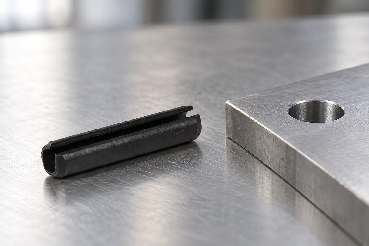
Roll pin sizes involve more than one measurement. Start with the nominal diameter and nominal length. Then check the uninstalled free outside diameter (free OD), chamfer, and recommended receiving-hole range. The final hole tolerance depends on the pin type, joint function, host material, and assembly method.
The table below covers ISO 8752:2009 heavy-duty metric slotted spring pins. It does not apply to coiled pins, light-duty slotted pins, inch pins, or solid dowel pins.
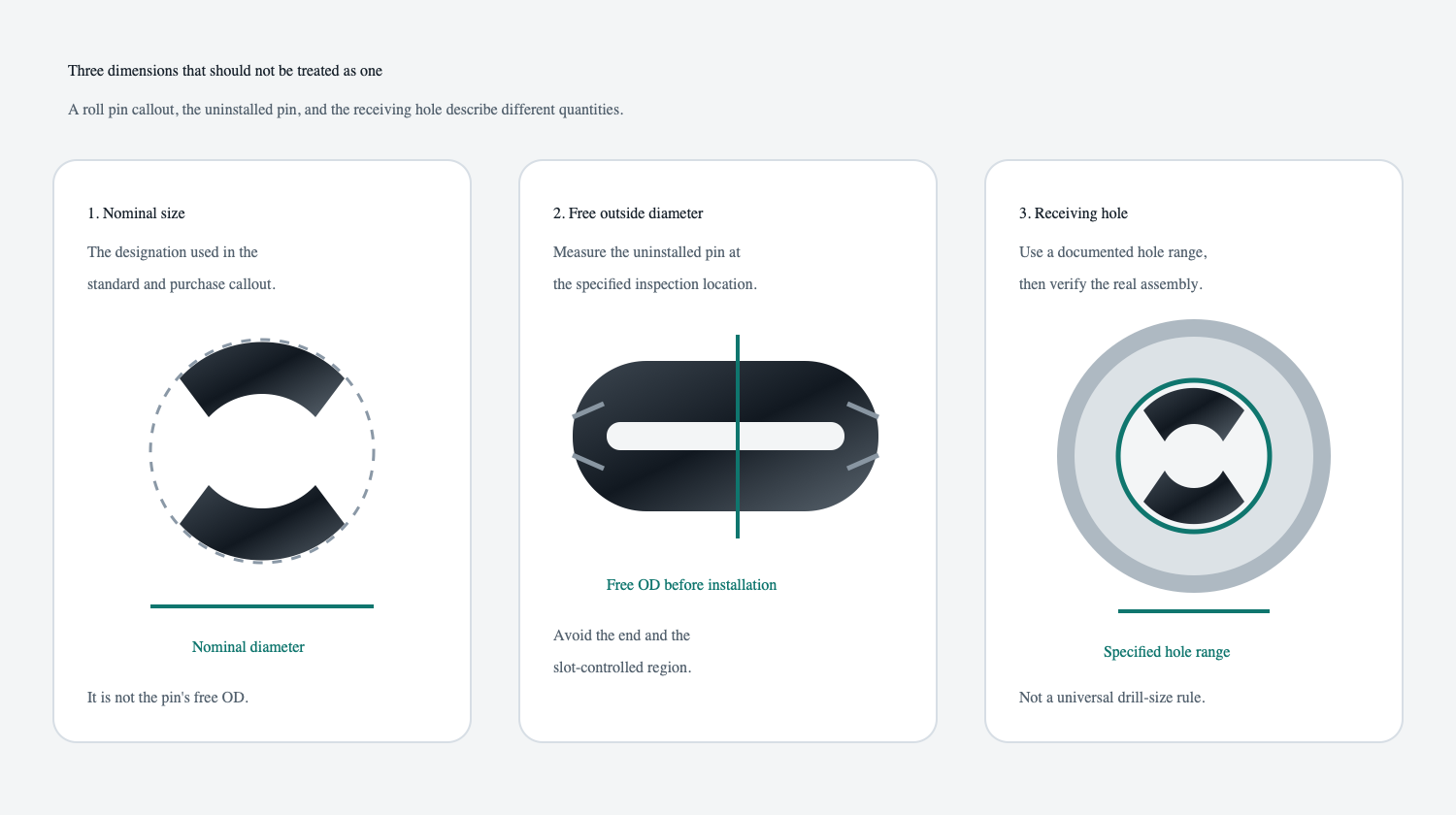
A slotted spring-pin callout uses nominal diameter × nominal length. The first value identifies the pin size. That value does not necessarily match the free outside diameter measured before installation. The second value is the nominal end-to-end length.
Free OD is the physical outside diameter of the uninstalled pin. The slot allows the pin to compress as it enters the receiving hole, so its free OD is specified separately from nominal diameter. Treat the two values as different drawing and inspection quantities.
Chamfer is another separate geometric feature. It provides a lead-in at the end of the pin, but it does not redefine nominal diameter or nominal length. In a dimensional review, identify the part designation, the inspectable free-pin dimension, and the feature that guides installation.
Keep these dimensions labeled on a drawing or RFQ rather than writing a bare diameter and expecting the receiver to infer its meaning. Pair nominal diameter with nominal length for identification. Reserve free OD and chamfer fields for the applicable specification or inspection requirement.
The following values are a SPIROL engineering reference for ISO 8752 metric slotted pins. They are not a universal roll-pin chart, and they are not proof of TG Eugene dimensions, tolerances, stock, or conformity. The scope here is intentionally limited to selected nominal diameters from 2 to 12 mm. Use the limits only within that defined product scope.
| Nominal diameter (mm) | Free OD minimum (mm) | Free OD maximum (mm) | Recommended hole minimum (mm) | Recommended hole maximum (mm) |
|---|---|---|---|---|
| 2 | 2.3 | 2.4 | 2.00 | 2.10 |
| 3 | 3.3 | 3.5 | 3.00 | 3.10 |
| 4 | 4.4 | 4.6 | 4.00 | 4.12 |
| 5 | 5.4 | 5.6 | 5.00 | 5.12 |
| 6 | 6.4 | 6.7 | 6.00 | 6.12 |
| 8 | 8.5 | 8.8 | 8.00 | 8.15 |
| 10 | 10.5 | 10.8 | 10.00 | 10.15 |
| 12 | 12.5 | 12.8 | 12.00 | 12.18 |
Each row keeps the size designation separate from the physical and hole dimensions. A nominal 6 mm pin, for example, has a larger uninstalled free OD in this reference, while the recommended hole begins at the nominal diameter. That relationship does not turn 6 mm into a universal drill size; it only describes the cited ISO 8752 product scope.
Length and chamfer remain outside this comparison. Length must be specified in the diameter × length callout, while chamfer must be checked as its own lead-in feature when the drawing or inspection plan controls it. For supplied parts, verify the applicable standard, approved drawing, product specification, and supplier inspection data rather than treating this SPIROL table as TG Eugene dimensional evidence.
Use a micrometer for the free-OD check described in SPIROL’s guide. Place the measurement at least one pin diameter away from the end. This keeps the reading away from the end geometry and provides a defined axial measurement location.
The slot also controls part of the circumference. SPIROL excludes the 30°–40° region associated with the slot from the OD measurement, so the micrometer contacts must sit outside that region. A reading taken across the slot, on the chamfer, or too close to the end does not follow this method.
This method defines where to measure free OD; it does not by itself establish acceptance of a shipment. Supplier inspection may also depend on the specified standard, finish condition, drawing requirements, gaging method, and agreed documentation. Record the method with the result so engineering and purchasing do not compare unlike readings.
A recommended hole range is a design starting point, not a released hole specification for every assembly. First confirm the exact pin type and standard. A value for an ISO 8752 heavy-duty slotted pin should not be carried over to a coiled pin, a light-duty slotted variant, an inch pin, or a solid dowel pin.
Define what the pin must do in the joint. Retention, alignment, hinging, stopping, and torque-related connections place different demands on the pin and surrounding components. The hole decision must support the actual joint function rather than merely accept installation.
Review the host material and the support around the hole before freezing the tolerance. Hole behavior can differ with material condition and local geometry. Edge distance, wall support, hardened edges, countersinks or other lead-ins, burrs, and casting draft can affect how the pin starts, compresses, and seats. This remains true even when the nominal hole value appears to match a reference range.
Alignment between mating holes also matters. A nominally correct hole pair can still create an assembly problem when the axes do not align or when the manufacturing sequence leaves an offset. Define whether parts are drilled together or separately, how the holes are located, and which component controls the fit.
Connect the tolerance to the manufacturing and inspection process. Drilling, reaming, punching, molding, or casting can leave different edge and hole conditions. Specify the finished requirement the supplier must verify, including any lead-in, burr, or alignment controls that affect assembly.
Application validation becomes necessary when the joint conditions differ from the table’s scope, when installation behavior is sensitive, or when service requirements cannot be established from dimensional fit alone. Use trials or the project’s approved validation method before releasing the final hole. Do not infer load, life, hardness, finish allowance, or service performance from the reference range.
Once engineering has defined the application-specific hole, purchasing needs a controlled set of inputs. Identify the standard and pin type, nominal diameter × nominal length, required material and finish, receiving-hole specification, quantity, drawing revision, and inspection documentation. Add any acceptance method that the supplier must follow instead of relying on a generic “roll pin” description.
Separate required values from items that remain subject to supplier confirmation. If a drawing cites ISO 8752 and adds project-specific controls, state which requirement governs where they differ. This prevents a catalog table from replacing the released roll pin specifications during quotation or incoming inspection.
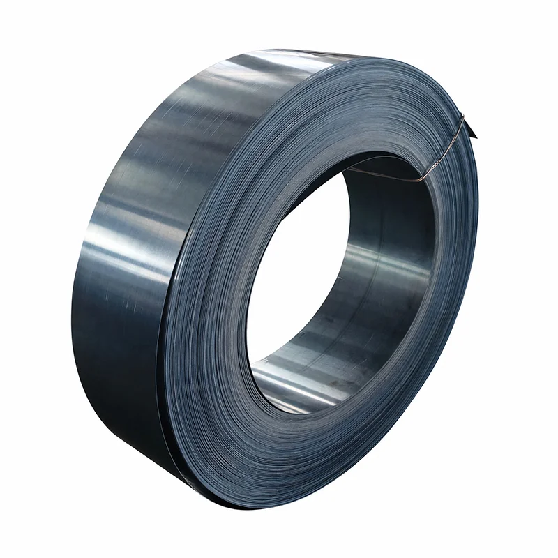
TG Eugene’s public page presents a 65Mn, black-oxide ISO 8752 heavy-duty slotted spring pin. That product identity does not show that its supplied dimensions match the SPIROL table. It also does not establish stock, interchangeability, loads, or tolerances for a specific order.
Send the drawing and required inputs for supplier confirmation. Ask the supplier to confirm the precise supplied dimensions, tolerance basis, material condition, finish, inspection method, and documentation against the current drawing revision. Keep the receiving-hole requirement in the same handoff so pin and host-part assumptions can be checked together.
A roll pin callout normally uses nominal diameter × nominal length. Do not use the uninstalled free outside diameter as the nominal size because a slotted spring pin is intentionally larger before installation.
The receiving hole depends on the exact pin type, standard, host material, and joint conditions. For an ISO 8752 slotted spring pin, use the applicable standard or approved supplier data as a starting range. Engineering should release the final hole tolerance on the drawing.