Taper pin sizes cannot be read from one diameter alone. A usable callout identifies the standard, unit system, reference diameter, length, taper direction, and mating-hole requirement. Miss one of those fields, and two suppliers can quote parts that share a size label but do not seat at the same depth.
The first check is the governing standard. ISO 2339 covers unhardened metric taper pins, while inch drawings may follow a different convention. The drawing should control the system directly instead of asking a supplier to infer it from an old part number.
Metric and inch taper pins perform a similar locating or fastening job, but their designations are not interchangeable. A common metric taper is 1:50. A common inch taper is 1:48, often described as 1/4 inch per foot. That difference changes the diameter growth over the pin length.
The reference diameter also matters. Metric taper-pin guidance commonly identifies the nominal diameter at the small end. Inch commercial practice commonly identifies it at the large end. Confirm the applicable standard before placing a diameter symbol on the drawing.
| Drawing item | Metric system to verify | Inch system to verify | Why it matters |
|---|---|---|---|
| Taper rate | Often 1:50 | Often 1:48 | Controls diameter change along the length |
| Nominal diameter location | Often the small end | Often the large end | Changes what the same diameter value describes |
| Length | Read from the selected standard | Read from the selected standard | Controls seating position and available engagement |
| Hole preparation | Matching metric taper system | Matching inch taper system | A straight drilled hole does not define the final seat |
These are system-level differences, not a substitute for the current standard. The pin drawing and the mating-part drawing should cite the same approved convention. Never convert a nominal size by changing millimeters to inches while leaving the taper and reference point unchanged.
Read the callout in a fixed sequence. This prevents a familiar size from hiding an incomplete specification.
Confirm the full standard and edition. Write the exact ISO, DIN, ASME, or other approved document. A family name such as “taper dowel” does not define the dimensional convention.
Confirm metric or inch practice. The unit system affects the taper ratio and may affect the reference diameter. Do not mix a metric nominal diameter with an inch reamer convention.
Locate the nominal diameter. Mark whether the stated diameter belongs at the small end, large end, or another defined gauge location. This is the most important check when reviewing a converted drawing.
Read the pin length from the correct end points. Keep chamfers, rounded ends, and any extraction feature separate from the controlled working length unless the standard says otherwise.
Show insertion direction and seating requirement. The assembly drawing should make clear which side receives the small end and what final position controls acceptance.
Define the mating tapered hole. State the reamer or taper system, reference diameter, depth, finish requirement, and inspection method needed by the application.
If an old drawing includes only a size such as “6 × 40,” stop before ordering. The numbers may describe a nominal diameter and length, but they do not prove the standard, reference end, material condition, or hole convention.
A unit conversion does not convert the product system. Suppose a legacy inch drawing lists a large-end diameter and uses a 1:48 taper. Replacing the inch diameter with its millimeter equivalent does not create an ISO 2339 callout. The metric family may use a 1:50 taper and identify nominal diameter at the small end. The converted value would describe a different location on a different cone.
Handle this change as an engineering revision. Keep the original callout, identify the proposed standard, compare taper, reference diameter, length, ends, material condition, and mating-hole tooling, and record approval. This review is especially important when existing reamers, gauges, or service parts must remain usable.
Procurement should not approve “equivalent” parts before engineering resolves those interfaces. A supplier can confirm manufacturability, but the assembly owner must decide whether the resulting seat and interchangeability satisfy the design.
A taper pin seats by matching its conical surface to a prepared tapered hole. Drilling establishes the starting hole. Reaming creates the final taper and seating relationship. The drawing should therefore control both components rather than treating the pin as a standalone catalog item.
Specify the functional result. If the pin locates two parts, identify the required assembled position and repeatability. If it retains a component, state the permitted seating range and removal method. If the joint will be serviced, provide access for extraction without adding an unapproved feature to the pin.
Do not set the final hole by copying the small-end diameter into a straight-hole callout. The tapered surface, gauge depth, and seating position determine the fit. Production should use the tool and inspection method approved for the selected standard and application.
A caliper reading at an arbitrary point cannot verify a taper pin by itself. A practical inspection plan starts with part identity and then checks the features that affect assembly.
Record the measurement method with the result. A value without its reference location can look precise while describing the wrong section of the pin.
Before releasing a request for quotation, confirm the following fields:
This checklist is more reliable than choosing from a size chart first. It lets engineering approve the interface before purchasing compares price and lead time. It also prevents a supplier from filling a missing drawing field with its own house convention.
Before RFQ release, engineering should reconcile four records. The standard reference must match the intended unit system and taper. The drawing must locate the nominal diameter at the point defined by that standard. The mating-part drawing must specify a compatible tapered hole and seating direction. The inspection plan must then use the same references when it records acceptance.
Place those checks in the drawing review rather than in email notes. If a supplier proposes a different standard, diameter reference, hole process, or gauge method, record the deviation and obtain approval before manufacture. Purchasing can then compare quotations against one controlled interface instead of comparing nominal size labels. Incoming inspection should retain the approved revision, measurement method, and result so a future replacement order does not repeat the interpretation work.
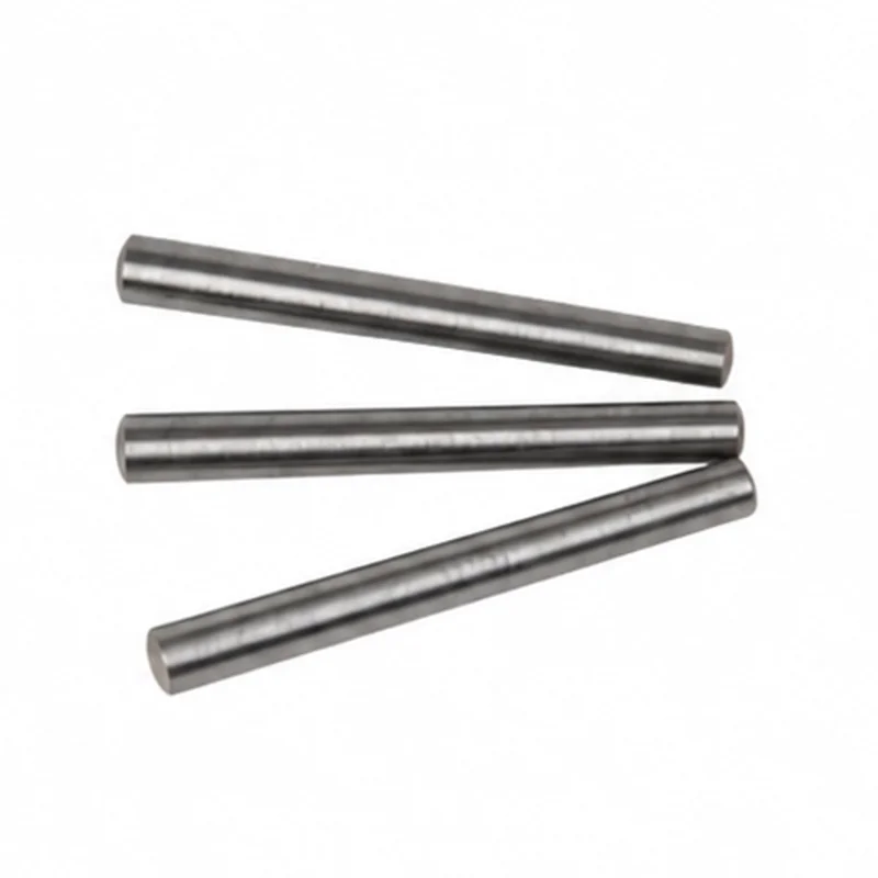
After the drawing is controlled, use the TG Eugene locating-pin product page and the wider product catalog to identify a candidate family for technical review. The page supports product-form recognition only; the standard identity and approved drawing remain the dimensional authority.