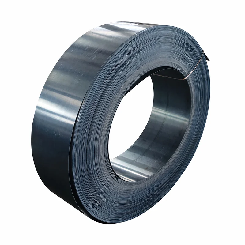
When a mechanical design engineer in Stuttgart encountered a delayed drive-module build because he could not promptly obtain accurate DIN 471 size and tolerance data, he selected a ring from an incomplete supplier sheet and released the shaft-groove drawing for assembly. The ring would not fully seat; after a trial run, the retained component moved axially. Inspection showed that the event was not simply a defective part: the nominal shaft, groove geometry, ring series, and assembly method had not been specified as one interface.
Summary: An external retaining ring is selected from the shaft’s nominal diameter and the matching groove data, then verified for material, finish, load case, and controlled installation. DIN 471 defines dimensional interchangeability for external retaining rings; it is not a product certification or proof that a particular ring is fit for every load. Start with the current standard table and the drawing’s groove callout, inspect the installed seating condition, and retain lot-level evidence where the application is safety- or downtime-critical.
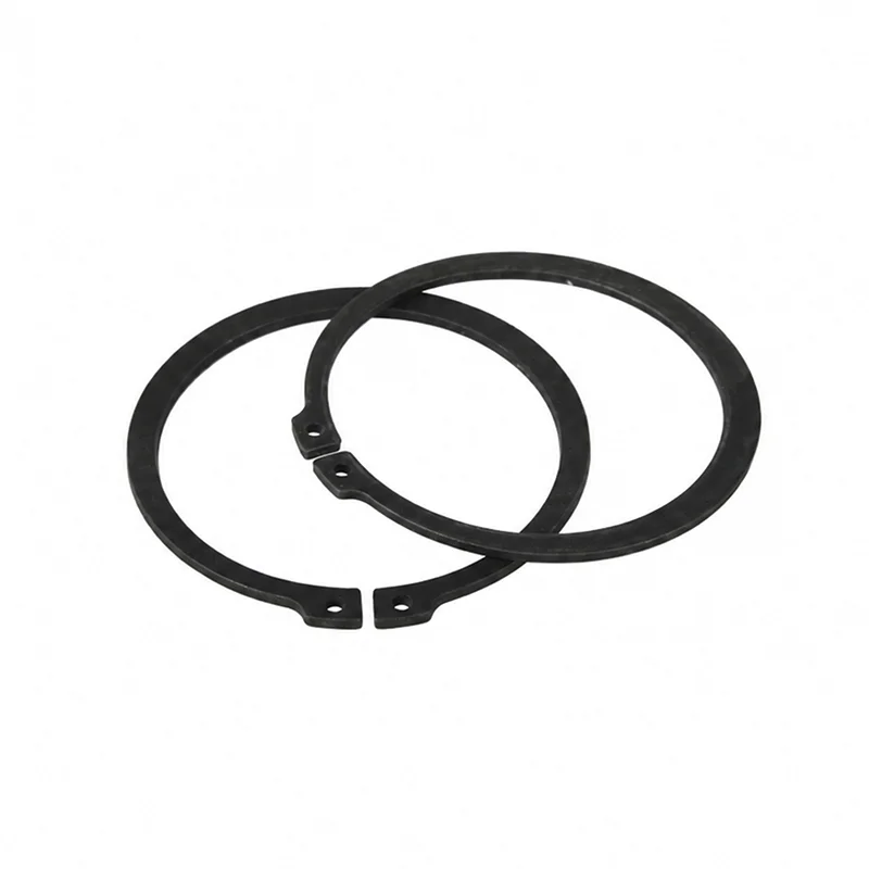
An external retaining ring is a spring element that expands over a shaft and contracts into a circumferential groove. Its job is to create an axial stop, usually in combination with a shoulder, spacer, bearing, or hub; it is not a substitute for a positive shaft shoulder when large reversing loads or impact can occur. The relevant nominal size is the shaft diameter identified by the standard series, but the ring’s functional location comes from the groove diameter, groove width, corner condition, and adjacent-part geometry.
A standard external retaining ring is therefore an interface component, not an isolated commodity. DIN 471 covers retaining rings for shafts and their associated dimensions; a buyer should request the edition used on the drawing and avoid mixing a catalogue’s nominal-size label with an unverified groove table. Where a fit system is part of the assembly, ISO 286-1 provides the common language for linear size tolerances and deviations. One millimetre-scale drawing omission can produce a visible non-seating condition even when the supplied ring itself is within its stated product specification.
Before calculating capacity, identify the load direction and duty cycle. A ring that is only positioning a lightly loaded cover sees a different risk profile from one retaining a bearing under vibration, thermal cycling, or repeated thrust reversal. The conservative design question is whether the groove face and the retained component keep the ring loaded squarely; a tilted contact path can concentrate force at one portion of the ring.
Axial force moves from the retained component to the ring face, then into the groove sidewall and shaft. The groove is often the governing feature because local yielding, burrs, chamfers that intrude into the contact face, or insufficient wall thickness can reduce practical retention long before a ring appears damaged. Specify the direction of the service force, whether it reverses, the operating temperature, corrosion exposure, and the maximum assembly speed as design inputs.
Use the current DIN 471 data for the nominal shaft range and confirm every paired feature on the controlled drawing. Measure groove diameter and width with a method that suits the tolerance and access; a calibrated micrometer, groove micrometer, optical comparator, or CMM may be appropriate. Treat the measurement system as part of the control plan: ISO 14253-1 explains how measurement uncertainty affects decisions about proving conformance or nonconformance to specification.
There is no universal published working-load number that safely replaces application validation. For critical assemblies, define an axial push-out or retention test that represents the actual force direction, temperature, and cycle count; document the fixture, sample condition, acceptance criterion, and result. A visual seating inspection is valuable, but it does not demonstrate fatigue or vibration performance on its own.
The unit price of a retaining ring is usually small relative to the cost of opening a gearbox, sorting an assembly lot, or holding a shipment. An illustrative calculation makes the point: if a 20-minute rework event affects 30 units, it consumes 10 labour-hours before spare parts, freight, line interruption, and warranty exposure are counted. Total-cost decisions should therefore fund a controlled drawing review and incoming verification where the consequence of axial release is material.
The best option depends on required axial location, serviceability, shaft space, assembly access, and failure consequence. The following comparison is qualitative; it does not replace a load-path calculation or application test.
| Retention method | Performance and compatibility | Assembly and maintenance | Unit-cost tendency | TCO consideration |
|---|---|---|---|---|
| External retaining ring in a groove | Compact axial stop on a grooved shaft; compatible with repeatable service access when the groove is correct. | Fast with suitable pliers and inspection; removal can damage a ring or surrounding finish. | Low to moderate. | Favourable when the groove is controlled and disassembly is planned. |
| Threaded nut and washer | Can provide adjustable clamp or retention; requires thread length and locking strategy. | Tool access and torque control are needed; re-tightening may be a maintenance item. | Moderate. | Higher assembly time may be justified for adjustable preload. |
| Machined shaft shoulder | Robust positive location in one direction; may need a separate method on the opposite side. | No ring installation at the shoulder; shaft machining is less flexible after release. | Cost moves into shaft manufacture. | Can reduce assembly risk where a fixed stop is sufficient. |
| Collar or clamp assembly | Useful where machining a groove is undesirable; performance depends on clamp design and surface condition. | Requires access, tightening control, and space around the shaft. | Moderate to high. | May simplify prototypes but adds parts and process controls. |
Do not treat a nominal diameter as a complete purchase description. The controlled selection should connect the shaft’s nominal size to the standard’s ring thickness, free-state geometry, groove diameter, groove width, edge condition, and the clearance needed for the retained part. Record the DIN471 circlip dimensions alongside the drawing revision so the selected ring and groove data remain traceable. The table below is a drawing-review guide rather than a substitute for the copyrighted standard’s dimensional table.
| Selection input | What to record | Why it changes the decision | Verification route |
|---|---|---|---|
| Nominal shaft size | Metric nominal diameter and the exact standard edition. | Identifies the applicable ring and groove series. | Controlled drawing and current DIN 471 table. |
| Groove geometry | Diameter, width, corner/edge condition, and tolerance. | Controls seating and sidewall contact, not merely ring fit over the shaft. | Dimensional inspection with suitable calibrated equipment. |
| Retained-part geometry | Bore/chamfer, washer or bearing face, clearance to the ring. | Prevents interference, skewed loading, and loss of usable contact face. | Section view, tolerance stack, and trial assembly. |
| Material and environment | Material grade, finish, temperature, media, and corrosion exposure. | Changes spring behaviour, corrosion risk, and documentation needs. | Material declaration; finish/process specification where applicable. |
| Service load | Axial direction, peak force, reversal, shock, and cycles. | Determines whether an application retention test is required. | Documented calculation and representative axial test. |
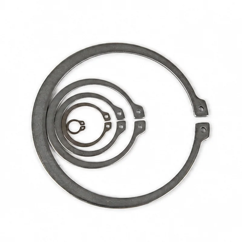
DIN 471 is a dimensional standard for external retaining rings for shafts. It helps parties communicate standardized geometry and associated groove dimensions; it is not a product certification, a blanket material approval, or evidence of fitness for a particular machine. A purchase order that says only “to DIN 471” can still leave material condition, finish, traceability, inspection level, packaging, and application validation unresolved. The DIN471 circlip installation work instruction should likewise define the approved tool and seating check.
Use standards according to their scope. ISO 286-1 supports the expression of size tolerances and fits; ISO 14253-1 addresses rules for proving conformance or nonconformance while considering measurement uncertainty; ISO 9227 is a salt-spray test method, not a durability certification for every corrosion environment. For machinery placed in the EU, the applicable legal framework depends on the finished machine, its intended use, and the claims made by its economic operator—component conformity must not be overstated as machine compliance.
Unsupported material, corrosion, lifecycle, or certification claims create commercial risk: they can trigger incoming rejection, requalification work, delayed customs or project documentation, and disputes over warranty scope. Align the drawing, inspection plan, supplier documentation, and end-market requirements before making such claims.
For sourcing discussions, Eugene can review drawings and production requirements for standard-series and custom fastener work; the useful starting point is a complete interface specification, not a nominal-size request alone. See the DIN471 circlip category when comparing the product family with the drawing requirements, and use this guide to choosing retaining rings for shafts and bores to frame the shaft-versus-bore choice.
“External snap ring” is a broader descriptive term for a ring that locates in a shaft groove. A DIN 471 designation should be used only when the relevant geometry is being specified to that standard; confirm the edition and the mating groove data instead of equating every external ring by appearance.
Verify that the ring is fully seated around the groove, that its lugs and body are not damaged, and that the retained part bears against the intended ring face without interference. Use correctly sized ring pliers and a controlled work instruction; if the application is critical, add a documented axial retention check after assembly.
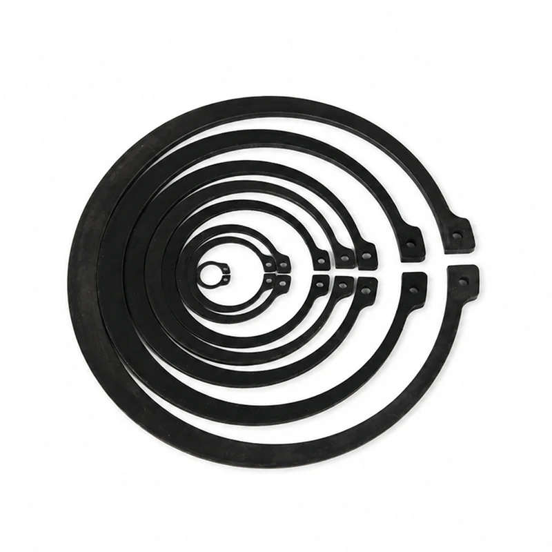
Reuse should not be assumed. Removal can permanently alter spring behaviour, nick an edge, or damage a corrosion-protective finish; follow the approved drawing, supplier guidance, and site quality procedure. When condition cannot be verified economically, replacement is the more controlled action.
No. Corrosion performance depends on the alloy, surface condition, chlorides or other media, temperature, crevices, and the surrounding assembly. Define the environment and qualification method; do not specify a material name as a substitute for an exposure assessment.
Request the controlled part description, drawing revision, material and finish requirements, inspection or sampling expectations, packaging condition, and traceability level appropriate to the application. Eugene can use that information to align a standard-series or drawing-led enquiry with production controls without implying unverified approvals.
Keep the standard edition, drawing revision, dimensional evidence, assembly result, and any application-test record together in the engineering file. The lasting principle is simple: a retaining ring is only as dependable as the groove, load path, and verification plan that make it functional.
ISO 286-1:2010 — ISO code system for tolerances on linear sizes
ISO 9227:2017 — Corrosion tests in artificial atmospheres: Salt spray tests
ISO 14253-1:2017 — Inspection by measurement of workpieces and measuring equipment
Regulation (EU) 2023/1230 on machinery
At the decision moment, send Eugene the shaft drawing, environment, quantity, and verification needs so the retention interface can be reviewed before manufacture. For equipment-specific context, see Eugene’s machinery manufacturing solution, then discuss an external retaining-ring requirement with Eugene.